Search Results: "chip"

9 January 2022

Matthew Garrett: Pluton is not (currently) a threat to software freedom

At CES this week, Lenovo announced that their new Z-series laptops would ship with AMD processors that incorporate Microsoft's Pluton security chip. There's a fair degree of cynicism around whether Microsoft have the interests of the industry as a whole at heart or not, so unsurprisingly people have voiced concerns about Pluton allowing for platform lock-in and future devices no longer booting non-Windows operating systems. Based on what we currently know, I think those concerns are understandable but misplaced.

But first it's helpful to know what Pluton actually is, and that's hard because Microsoft haven't actually provided much in the way of technical detail. The best I've found is a discussion of Pluton in the context of Azure Sphere, Microsoft's IoT security platform. This, in association with the block diagrams on page 12 and 13 of this slidedeck, suggest that Pluton is a general purpose security processor in a similar vein to Google's Titan chip. It has a relatively low powered CPU core, an RNG, and various hardware cryptography engines - there's nothing terribly surprising here, and it's pretty much the same set of components that you'd find in a standard Trusted Platform Module of the sort shipped in pretty much every modern x86 PC. But unlike Titan, Pluton seems to have been designed with the explicit goal of being incorporated into other chips, rather than being a standalone component. In the Azure Sphere case, we see it directly incorporated into a Mediatek chip. In the Xbox Series devices, it's incorporated into the SoC. And now, we're seeing it arrive on general purpose AMD CPUs.

Microsoft's announcement says that Pluton can be shipped in three configurations:as the Trusted Platform Module; as a security processor used for non-TPM scenarios like platform resiliency; or OEMs can choose to ship with Pluton turned off. What we're likely to see to begin with is the former - Pluton will run firmware that exposes a Trusted Computing Group compatible TPM interface. This is almost identical to the status quo. Microsoft have required that all Windows certified hardware ship with a TPM for years now, but for cost reasons this is often not in the form of a separate hardware component. Instead, both Intel and AMD provide support for running the TPM stack on a component separate from the main execution cores on the system - for Intel, this TPM code runs on the Management Engine integrated into the chipset, and for AMD on the Platform Security Processor that's integrated into the CPU package itself.

So in this respect, Pluton changes very little; the only difference is that the TPM code is running on hardware dedicated to that purpose, rather than alongside other code. Importantly, in this mode Pluton will not do anything unless the system firmware or OS ask it to. Pluton cannot independently block the execution of any other code - it knows nothing about the code the CPU is executing unless explicitly told about it. What the OS can certainly do is ask Pluton to verify a signature before executing code, but the OS could also just verify that signature itself. Windows can already be configured to reject software that doesn't have a valid signature. If Microsoft wanted to enforce that they could just change the default today, there's no need to wait until everyone has hardware with Pluton built-in.

The two things that seem to cause people concerns are remote attestation and the fact that Microsoft will be able to ship firmware updates to Pluton via Windows Update. I've written about remote attestation before, so won't go into too many details here, but the short summary is that it's a mechanism that allows your system to prove to a remote site that it booted a specific set of code. What's important to note here is that the TPM (Pluton, in the scenario we're talking about) can't do this on its own - remote attestation can only be triggered with the aid of the operating system. Microsoft's Device Health Attestation is an example of remote attestation in action, and the technology definitely allows remote sites to refuse to grant you access unless you booted a specific set of software. But there are two important things to note here: first, remote attestation cannot prevent you from booting whatever software you want, and second, as evidenced by Microsoft already having a remote attestation product, you don't need Pluton to do this! Remote attestation has been possible since TPMs started shipping over two decades ago.

The other concern is Microsoft having control over the firmware updates. The context here is that TPMs are not magically free of bugs, and sometimes these can have security consequences. One example is Infineon TPMs producing weak RSA keys, a vulnerability that could be rectified by a firmware update to the TPM. Unfortunately these updates had to be issued by the device manufacturer rather than Infineon being able to do so directly. This meant users had to wait for their vendor to get around to shipping an update, something that might not happen at all if the machine was sufficiently old. From a security perspective, being able to ship firmware updates for the TPM without them having to go through the device manufacturer is a huge win.

Microsoft's obviously in a position to ship a firmware update that modifies the TPM's behaviour - there would be no technical barrier to them shipping code that resulted in the TPM just handing out your disk encryption secret on demand. But Microsoft already control the operating system, so they already have your disk encryption secret. There's no need for them to backdoor the TPM to give them something that the TPM's happy to give them anyway. If you don't trust Microsoft then you probably shouldn't be running Windows, and if you're not running Windows Microsoft can't update the firmware on your TPM.

So, as of now, Pluton running firmware that makes it look like a TPM just isn't a terribly interesting change to where we are already. It can't block you running software (either apps or operating systems). It doesn't enable any new privacy concerns. There's no mechanism for Microsoft to forcibly push updates to it if you're not running Windows.

Could this change in future? Potentially. Microsoft mention another use-case for Pluton "as a security processor used for non-TPM scenarios like platform resiliency", but don't go into any more detail. At this point, we don't know the full set of capabilities that Pluton has. Can it DMA? Could it play a role in firmware authentication? There are scenarios where, in theory, a component such as Pluton could be used in ways that would make it more difficult to run arbitrary code. It would be reassuring to hear more about what the non-TPM scenarios are expected to look like and what capabilities Pluton actually has.

But let's not lose sight of something more fundamental here. If Microsoft wanted to block free operating systems from new hardware, they could simply mandate that vendors remove the ability to disable secure boot or modify the key databases. If Microsoft wanted to prevent users from being able to run arbitrary applications, they could just ship an update to Windows that enforced signing requirements. If they want to be hostile to free software, they don't need Pluton to do it.

(Edit: it's been pointed out that I kind of gloss over the fact that remote attestation is a potential threat to free software, as it theoretically allows sites to block access based on which OS you're running. There's various reasons I don't think this is realistic - one is that there's just way too much variability in measurements for it to be practical to write a policy that's strict enough to offer useful guarantees without also blocking a number of legitimate users, and the other is that you can just pass the request through to a machine that is running the appropriate software and have it attest for you. The fact that nobody has actually bothered to use remote attestation for this purpose even though most consumer systems already ship with TPMs suggests that people generally agree with me on that)

comment count unavailable comments

4 January 2022

Jonathan McDowell: Upgrading from a CC2531 to a CC2538 Zigbee coordinator

Previously I setup a CC2531 as a Zigbee coordinator for my home automation. This has turned out to be a good move, with the 4 gang wireless switch being particularly useful. However the range of the CC2531 is fairly poor; it has a simple PCB antenna. It s also a very basic device. I set about trying to improve the range and scalability and settled upon a CC2538 + CC2592 device, which feature an MMCX antenna connector. This device also has the advantage that it s ARM based, which I m hopeful means I might be able to build some firmware myself using a standard GCC toolchain. For now I fetched the JetHome firmware from https://github.com/jethome-ru/zigbee-firmware/tree/master/ti/coordinator/cc2538_cc2592 (JH_2538_2592_ZNP_UART_20211222.hex) - while it s possible to do USB directly with the CC2538 my board doesn t have those bits so going the external USB UART route is easier. The device had some existing firmware on it, so I needed to erase this to force a drop into the boot loader. That means soldering up the JTAG pins and hooking it up to my Bus Pirate for OpenOCD goodness.
OpenOCD config
source [find interface/buspirate.cfg]
buspirate_port /dev/ttyUSB1
buspirate_mode normal
buspirate_vreg 1
buspirate_pullup 0
transport select jtag
source [find target/cc2538.cfg]
Steps to erase
$ telnet localhost 4444
Trying ::1...
Trying 127.0.0.1...
Connected to localhost.
Escape character is '^]'.
Open On-Chip Debugger
> mww 0x400D300C 0x7F800
> mww 0x400D3008 0x0205
> shutdown
shutdown command invoked
Connection closed by foreign host.
At that point I can switch to the UART connection (on PA0 + PA1) and flash using cc2538-bsl:
$ git clone https://github.com/JelmerT/cc2538-bsl.git
$ cc2538-bsl/cc2538-bsl.py -p /dev/ttyUSB1 -e -w -v ~/JH_2538_2592_ZNP_UART_20211222.hex
Opening port /dev/ttyUSB1, baud 500000
Reading data from /home/noodles/JH_2538_2592_ZNP_UART_20211222.hex
Firmware file: Intel Hex
Connecting to target...
CC2538 PG2.0: 512KB Flash, 32KB SRAM, CCFG at 0x0027FFD4
Primary IEEE Address: 00:12:4B:00:22:22:22:22
    Performing mass erase
Erasing 524288 bytes starting at address 0x00200000
    Erase done
Writing 524256 bytes starting at address 0x00200000
Write 232 bytes at 0x0027FEF88
    Write done
Verifying by comparing CRC32 calculations.
    Verified (match: 0x74f2b0a1)
I then wanted to migrate from the old device to the new without having to repair everything. So I shut down Home Assistant and backed up the CC2531 network information using zigpy-znp (which is already installed for Home Assistant):
python3 -m zigpy_znp.tools.network_backup /dev/zigbee > cc2531-network.json
I copied the backup to cc2538-network.json and modified the coordinator_ieee to be the new device s MAC address (rather than end up with 2 devices claiming the same MAC if/when I reuse the CC2531) and did:
python3 -m zigpy_znp.tools.network_restore --input cc2538-network.json /dev/ttyUSB1
The old CC2531 needed unplugged first, otherwise I got an RuntimeError: Network formation refused, RF environment is likely too noisy. Temporarily unscrew the antenna or shield the coordinator with metal until a network is formed. error. After that I updated my udev rules to map the CC2538 to /dev/zigbee and restarted Home Assistant. To my surprise it came up and detected the existing devices without any extra effort on my part. However that resulted in 2 coordinators being shown in the visualisation, with the old one turning up as unk_manufacturer. Fixing that involved editing /etc/homeassistant/.storage/core.device_registry and removing the entry which had the old MAC address, removing the device entry in /etc/homeassistant/.storage/zha.storage for the old MAC and then finally firing up sqlite to modify the Zigbee database:
$ sqlite3 /etc/homeassistant/zigbee.db
SQLite version 3.34.1 2021-01-20 14:10:07
Enter ".help" for usage hints.
sqlite> DELETE FROM devices_v6 WHERE ieee = '00:12:4b:00:11:11:11:11';
sqlite> DELETE FROM endpoints_v6 WHERE ieee = '00:12:4b:00:11:11:11:11';
sqlite> DELETE FROM in_clusters_v6 WHERE ieee = '00:12:4b:00:11:11:11:11';
sqlite> DELETE FROM neighbors_v6 WHERE ieee = '00:12:4b:00:11:11:11:11' OR device_ieee = '00:12:4b:00:11:11:11:11';
sqlite> DELETE FROM node_descriptors_v6 WHERE ieee = '00:12:4b:00:11:11:11:11';
sqlite> DELETE FROM out_clusters_v6 WHERE ieee = '00:12:4b:00:11:11:11:11';
sqlite> .quit
So far it all seems a bit happier than with the CC2531; I ve been able to pair a light bulb that was previously detected but would not integrate, which suggests the range is improved. (This post another in the set of things I should write down so I can just grep my own website when I forget what I did to do foo .)

3 October 2021

Louis-Philippe V ronneau: ANC is not for me

Active noise cancellation (ANC) has been all the rage lately in the headphones and in-ear monitors market. It seems after Apple got heavily praised for their AirPods Pro, every somewhat serious electronics manufacturer released their own design incorporating this technology. The first headphones with ANC I remember trying on (in the early 2010s) were the Bose QuietComfort 15. Although the concept did work (they indeed cancelled some sounds), they weren't amazing and did a great job of convincing me ANC was some weird fad for people who flew often. The Sony WH-1000X M3 folded in their case As the years passed, chip size decreased, battery capacity improved and machine learning blossomed truly a perfect storm for the wireless ANC headphones market. I had mostly stayed a sceptic of this tech until recently a kind friend offered to let me try a pair of Sony WH-1000X M3. Having tested them thoroughly, I have to say I'm really tempted to buy them from him, as they truly are fantastic headphones1. They are very light, comfortable, work without a proprietary app and sound very good with the ANC on2 if a little bass-heavy for my taste3. The ANC itself is truly astounding and is leaps and bounds beyond what was available five years ago. It still isn't perfect and doesn't cancel ALL sounds, but transforms the low hum of the subway I find myself sitting in too often these days into a light *swoosh*. When you turn the ANC on, HVAC simply disappears. Most impressive to me is the way they completely cancel the dreaded sound of your footsteps resonating in your headphones when you walk with them. My old pair of Senheiser HD 280 Pro, with aftermarket sheepskin earpads I won't be keeping them though. Whilst I really like what Sony has achieved here, I've grown to understand ANC simply isn't for me. Some of the drawbacks of ANC somewhat bother me: the ear pressure it creates is tolerable, but is an additional energy drain over long periods of time and eventually gives me headaches. I've also found ANC accentuates the motion sickness I suffer from, probably because it messes up with some part of the inner ear balance system. Most of all, I found that it didn't provide noticeable improvements over good passive noise cancellation solutions, at least in terms of how high I have to turn the volume up to hear music or podcasts clearly. The human brain works in mysterious ways and it seems ANC cancelling a class of noises (low hums, constant noises, etc.) makes other noises so much more noticeable. People talking or bursty high pitched noises bothered me much more with ANC on than without. So for now, I'll keep using my trusty Senheiser HD 280 Pro4 at work and good in-ear monitors with Comply foam tips on the go.

  1. This blog post certainly doesn't aim to be a comprehensive review of these headphones. See Zeos' review if you want something more in-depth.
  2. As most ANC headphones, they don't sound as good when used passively through the 3.5mm port, but that's just a testament of how a great job Sony did of tuning the DSP.
  3. Easily fixed using an EQ.
  4. Retrofitted with aftermarket sheepskin earpads, they provide more than 32db of passive noise reduction.

28 September 2021

Jonathan McDowell: Adding Zigbee to my home automation

SonOff Zigbee Door Sensor My home automation setup has been fairly static recently; it does what we need and generally works fine. One area I think could be better is controlling it; we have access Home Assistant on our phones, and the Alexa downstairs can control things, but there are no smart assistants upstairs and sometimes it would be nice to just push a button to turn on the light rather than having to get my phone out. Thanks to the fact the UK generally doesn t have neutral wire in wall switches that means looking at something battery powered. Which means wifi based devices are a poor choice, and it s necessary to look at something lower power like Zigbee or Z-Wave. Zigbee seems like the better choice; it s a more open standard and there are generally more devices easily available from what I ve seen (e.g. Philips Hue and IKEA TR DFRI). So I bought a couple of Xiaomi Mi Smart Home Wireless Switches, and a CC2530 module and then ignored it for the best part of a year. Finally I got around to flashing the Z-Stack firmware that Koen Kanters kindly provides. (Insert rant about hardware manufacturers that require pay-for tool chains. The CC2530 is even worse because it s 8051 based, so SDCC should be able to compile for it, but the TI Zigbee libraries are only available in a format suitable for IAR s embedded workbench.) Flashing the CC2530 is a bit of faff. I ended up using the CCLib fork by Stephan Hadinger which supports the ESP8266. The nice thing about the CC2530 module is it has 2.54mm pitch pins so nice and easy to jumper up. It then needs a USB/serial dongle to connect it up to a suitable machine, where I ran Zigbee2MQTT. This scares me a bit, because it s a bunch of node.js pulling in a chunk of stuff off npm. On the flip side, it Just Works and I was able to pair the Xiaomi button with the device and see MQTT messages that I could then use with Home Assistant. So of course I tore down that setup and went and ordered a CC2531 (the variant with USB as part of the chip). The idea here was my test setup was upstairs with my laptop, and I wanted something hooked up in a more permanent fashion. Once the CC2531 arrived I got distracted writing support for the Desk Viking to support CCLib (and modified it a bit for Python3 and some speed ups). I flashed the dongle up with the Z-Stack Home 1.2 (default) firmware, and plugged it into the house server. At this point I more closely investigated what Home Assistant had to offer in terms of Zigbee integration. It turns out the ZHA integration has support for the ZNP protocol that the TI devices speak (I m reasonably sure it didn t when I first looked some time ago), so that seemed like a better option than adding the MQTT layer in the middle. I hit some complexity passing the dongle (which turns up as /dev/ttyACM0) through to the Home Assistant container. First I needed an override file in /etc/systemd/nspawn/hass.nspawn:
[Files]
Bind=/dev/ttyACM0:/dev/zigbee
[Network]
VirtualEthernet=true
(I m not clear why the VirtualEthernet needed to exist; without it networking broke entirely but I couldn t see why it worked with no override file.) A udev rule on the host to change the ownership of the device file so the root user and dialout group in the container could see it was also necessary, so into /etc/udev/rules.d/70-persistent-serial.rules went:
# Zigbee for HASS
SUBSYSTEM=="tty", ATTRS idVendor =="0451", ATTRS idProduct =="16a8", SYMLINK+="zigbee", \
	MODE="660", OWNER="1321926676", GROUP="1321926676"
In the container itself I had to switch PrivateDevices=true to PrivateDevices=false in the home-assistant.service file (which took me a while to figure out; yay for locking things down and then needing to use those locked down things). Finally I added the hass user to the dialout group. At that point I was able to go and add the integration with Home Assistant, and add the button as a new device. Excellent. I did find I needed a newer version of Home Assistant to get support for the button, however. I was still on 2021.1.5 due to upstream dropping support for Python 3.7 and not being prepared to upgrade to Debian 11 until it was actually released, so the version of zha-quirks didn t have the correct info. Upgrading to Home Assistant 2021.8.7 sorted that out. There was another slight problem. Range. Really I want to use the button upstairs. The server is downstairs, and most of my internal walls are brick. The solution turned out to be a TR DFRI socket, which replaced the existing ESP8266 wifi socket controlling the stair lights. That was close enough to the server to have a decent signal, and it acts as a Zigbee router so provides a strong enough signal for devices upstairs. The normal approach seems to be to have a lot of Zigbee light bulbs, but I have mostly kept overhead lights as uncontrolled - we don t use them day to day and it provides a nice fallback if the home automation has issues. Of course installing Zigbee for a single button would seem to be a bit pointless. So I ordered up a Sonoff door sensor to put on the front door (much smaller than expected - those white boxes on the door are it in the picture above). And I have a 4 gang wireless switch ordered to go on the landing wall upstairs. Now I ve got a Zigbee setup there are a few more things I m thinking of adding, where wifi isn t an option due to the need for battery operation (monitoring the external gas meter springs to mind). The CC2530 probably isn t suitable for my needs, as I ll need to write some custom code to handle the bits I want, but there do seem to be some ARM based devices which might well prove suitable

6 September 2021

Vincent Bernat: Switching to the i3 window manager

I have been using the awesome window manager for 10 years. It is a tiling window manager, configurable and extendable with the Lua language. Using a general-purpose programming language to configure every aspect is a double-edged sword. Due to laziness and the apparent difficulty of adapting my configuration about 3000 lines to newer releases, I was stuck with the 3.4 version, whose last release is from 2013. It was time for a rewrite. Instead, I have switched to the i3 window manager, lured by the possibility to migrate to Wayland and Sway later with minimal pain. Using an embedded interpreter for configuration is not as important to me as it was in the past: it brings both complexity and brittleness.
i3 dual screen setup
Dual screen desktop running i3, Emacs, some terminals, including a Quake console, Firefox, Polybar as the status bar, and Dunst as the notification daemon.
The window manager is only one part of a desktop environment. There are several options for the other components. I am also introducing them in this post.

i3: the window manager i3 aims to be a minimal tiling window manager. Its documentation can be read from top to bottom in less than an hour. i3 organize windows in a tree. Each non-leaf node contains one or several windows and has an orientation and a layout. This information arbitrates the window positions. i3 features three layouts: split, stacking, and tabbed. They are demonstrated in the below screenshot:
Example of layouts
Demonstration of the layouts available in i3. The main container is split horizontally. The first child is split vertically. The second one is tabbed. The last one is stacking.
Tree representation of the previous screenshot
Tree representation of the previous screenshot.
Most of the other tiling window managers, including the awesome window manager, use predefined layouts. They usually feature a large area for the main window and another area divided among the remaining windows. These layouts can be tuned a bit, but you mostly stick to a couple of them. When a new window is added, the behavior is quite predictable. Moreover, you can cycle through the various windows without thinking too much as they are ordered. i3 is more flexible with its ability to build any layout on the fly, it can feel quite overwhelming as you need to visualize the tree in your head. At first, it is not unusual to find yourself with a complex tree with many useless nested containers. Moreover, you have to navigate windows using directions. It takes some time to get used to. I set up a split layout for Emacs and a few terminals, but most of the other workspaces are using a tabbed layout. I don t use the stacking layout. You can find many scripts trying to emulate other tiling window managers but I did try to get my setup pristine of these tentatives and get a chance to familiarize myself. i3 can also save and restore layouts, which is quite a powerful feature. My configuration is quite similar to the default one and has less than 200 lines.

i3 companion: the missing bits i3 philosophy is to keep a minimal core and let the user implements missing features using the IPC protocol:
Do not add further complexity when it can be avoided. We are generally happy with the feature set of i3 and instead focus on fixing bugs and maintaining it for stability. New features will therefore only be considered if the benefit outweighs the additional complexity, and we encourage users to implement features using the IPC whenever possible. Introduction to the i3 window manager
While this is not as powerful as an embedded language, it is enough for many cases. Moreover, as high-level features may be opinionated, delegating them to small, loosely coupled pieces of code keeps them more maintainable. Libraries exist for this purpose in several languages. Users have published many scripts to extend i3: automatic layout and window promotion to mimic the behavior of other tiling window managers, window swallowing to put a new app on top of the terminal launching it, and cycling between windows with Alt+Tab. Instead of maintaining a script for each feature, I have centralized everything into a single Python process, i3-companion using asyncio and the i3ipc-python library. Each feature is self-contained into a function. It implements the following components:
make a workspace exclusive to an application
When a workspace contains Emacs or Firefox, I would like other applications to move to another workspace, except for the terminal which is allowed to intrude into any workspace. The workspace_exclusive() function monitors new windows and moves them if needed to an empty workspace or to one with the same application already running.
implement a Quake console
The quake_console() function implements a drop-down console available from any workspace. It can be toggled with Mod+ . This is implemented as a scratchpad window.
back and forth workspace switching on the same output
With the workspace back_and_forth command, we can ask i3 to switch to the previous workspace. However, this feature is not restricted to the current output. I prefer to have one keybinding to switch to the workspace on the next output and one keybinding to switch to the previous workspace on the same output. This behavior is implemented in the previous_workspace() function by keeping a per-output history of the focused workspaces.
create a new empty workspace or move a window to an empty workspace
To create a new empty workspace or move a window to an empty workspace, you have to locate a free slot and use workspace number 4 or move container to workspace number 4. The new_workspace() function finds a free number and use it as the target workspace.
restart some services on output change
When adding or removing an output, some actions need to be executed: refresh the wallpaper, restart some components unable to adapt their configuration on their own, etc. i3 triggers an event for this purpose. The output_update() function also takes an extra step to coalesce multiple consecutive events and to check if there is a real change with the low-level library xcffib.
I will detail the other features as this post goes on. On the technical side, each function is decorated with the events it should react to:
@on(CommandEvent("previous-workspace"), I3Event.WORKSPACE_FOCUS)
async def previous_workspace(i3, event):
    """Go to previous workspace on the same output."""
The CommandEvent() event class is my way to send a command to the companion, using either i3-msg -t send_tick or binding a key to a nop command. The latter is used to avoid spawning a shell and a i3-msg process just to send a message. The companion listens to binding events and checks if this is a nop command.
bindsym $mod+Tab nop "previous-workspace"
There are other decorators to avoid code duplication: @debounce() to coalesce multiple consecutive calls, @static() to define a static variable, and @retry() to retry a function on failure. The whole script is a bit more than 1000 lines. I think this is worth a read as I am quite happy with the result.

dunst: the notification daemon Unlike the awesome window manager, i3 does not come with a built-in notification system. Dunst is a lightweight notification daemon. I am running a modified version with HiDPI support for X11 and recursive icon lookup. The i3 companion has a helper function, notify(), to send notifications using DBus. container_info() and workspace_info() uses it to display information about the container or the tree for a workspace.
Notification showing i3 tree for a workspace
Notification showing i3 s tree for a workspace

polybar: the status bar i3 bundles i3bar, a versatile status bar, but I have opted for Polybar. A wrapper script runs one instance for each monitor. The first module is the built-in support for i3 workspaces. To not have to remember which application is running in a workspace, the i3 companion renames workspaces to include an icon for each application. This is done in the workspace_rename() function. The icons are from the Font Awesome project. I maintain a mapping between applications and icons. This is a bit cumbersome but it looks great.
i3 workspaces in Polybar
For CPU, memory, brightness, battery, disk, and audio volume, I am relying on the built-in modules. Polybar s wrapper script generates the list of filesystems to monitor and they get only displayed when available space is low. The battery widget turns red and blinks slowly when running out of power. Check my Polybar configuration for more details.
Various modules for Polybar
Polybar displaying various information: CPU usage, memory usage, screen brightness, battery status, Bluetooth status (with a connected headset), network status (connected to a wireless network and to a VPN), notification status, and speaker volume.
For Bluetooh, network, and notification statuses, I am using Polybar s ipc module: the next version of Polybar can receive an arbitrary text on an IPC socket. The module is defined with a single hook to be executed at the start to restore the latest status.
[module/network]
type = custom/ipc
hook-0 = cat $XDG_RUNTIME_DIR/i3/network.txt 2> /dev/null
initial = 1
It can be updated with polybar-msg action "#network.send.XXXX". In the i3 companion, the @polybar() decorator takes the string returned by a function and pushes the update through the IPC socket. The i3 companion reacts to DBus signals to update the Bluetooth and network icons. The @on() decorator accepts a DBusSignal() object:
@on(
    StartEvent,
    DBusSignal(
        path="/org/bluez",
        interface="org.freedesktop.DBus.Properties",
        member="PropertiesChanged",
        signature="sa sv as",
        onlyif=lambda args: (
            args[0] == "org.bluez.Device1"
            and "Connected" in args[1]
            or args[0] == "org.bluez.Adapter1"
            and "Powered" in args[1]
        ),
    ),
)
@retry(2)
@debounce(0.2)
@polybar("bluetooth")
async def bluetooth_status(i3, event, *args):
    """Update bluetooth status for Polybar."""
The middle of the bar is occupied by the date and a weather forecast. The latest also uses the IPC mechanism, but the source is a Python script triggered by a timer.
Date and weather in Polybar
Current date and weather forecast for the day in Polybar. The data is retrieved with the OpenWeather API.
I don t use the system tray integrated with Polybar. The embedded icons usually look horrible and they all behave differently. A few years back, Gnome has removed the system tray. Most of the problems are fixed by the DBus-based Status Notifier Item protocol also known as Application Indicators or Ayatana Indicators for GNOME. However, Polybar does not support this protocol. In the i3 companion, The implementation of Bluetooth and network icons, including displaying notifications on change, takes about 200 lines. I got to learn a bit about how DBus works and I get exactly the info I want.

picom: the compositor I like having slightly transparent backgrounds for terminals and to reduce the opacity of unfocused windows. This requires a compositor.1 picom is a lightweight compositor. It works well for me, but it may need some tweaking depending on your graphic card.2 Unlike the awesome window manager, i3 does not handle transparency, so the compositor needs to decide by itself the opacity of each window. Check my configuration for details.

systemd: the service manager I use systemd to start i3 and the various services around it. My xsession script only sets some environment variables and lets systemd handles everything else. Have a look at this article from Micha G ral for the rationale. Notably, each component can be easily restarted and their logs are not mangled inside the ~/.xsession-errors file.3 I am using a two-stage setup: i3.service depends on xsession.target to start services before i3:
[Unit]
Description=X session
BindsTo=graphical-session.target
Wants=autorandr.service
Wants=dunst.socket
Wants=inputplug.service
Wants=picom.service
Wants=pulseaudio.socket
Wants=policykit-agent.service
Wants=redshift.service
Wants=spotify-clean.timer
Wants=ssh-agent.service
Wants=xiccd.service
Wants=xsettingsd.service
Wants=xss-lock.service
Then, i3 executes the second stage by invoking the i3-session.target:
[Unit]
Description=i3 session
BindsTo=graphical-session.target
Wants=wallpaper.service
Wants=wallpaper.timer
Wants=polybar-weather.service
Wants=polybar-weather.timer
Wants=polybar.service
Wants=i3-companion.service
Wants=misc-x.service
Have a look on my configuration files for more details.

rofi: the application launcher Rofi is an application launcher. Its appearance can be customized through a CSS-like language and it comes with several themes. Have a look at my configuration for mine.
Rofi as an application launcher
It can also act as a generic menu application. I have a script to control a media player and another one to select the wifi network. It is quite a flexible application.
Rofi as a wifi network selector
Rofi to select a wireless network

xss-lock and i3lock: the screen locker i3lock is a simple screen locker. xss-lock invokes it reliably on inactivity or before a system suspend. For inactivity, it uses the XScreenSaver events. The delay is configured using the xset s command. The locker can be invoked immediately with xset s activate. X11 applications know how to prevent the screen saver from running. I have also developed a small dimmer application that is executed 20 seconds before the locker to give me a chance to move the mouse if I am not away.4 Have a look at my configuration script.
Demonstration of xss-lock, xss-dimmer and i3lock with a 4 speedup.

The remaining components
  • autorandr is a tool to detect the connected display, match them against a set of profiles, and configure them with xrandr.
  • inputplug executes a script for each new mouse and keyboard plugged. This is quite useful to load the appropriate the keyboard map. See my configuration.
  • xsettingsd provides settings to X11 applications, not unlike xrdb but it notifies applications for changes. The main use is to configure the Gtk and DPI settings. See my article on HiDPI support on Linux with X11.
  • Redshift adjusts the color temperature of the screen according to the time of day.
  • maim is a utility to take screenshots. I use Prt Scn to trigger a screenshot of a window or a specific area and Mod+Prt Scn to capture the whole desktop to a file. Check the helper script for details.
  • I have a collection of wallpapers I rotate every hour. A script selects them using advanced machine learning algorithms and stitches them together on multi-screen setups. The selected wallpaper is reused by i3lock.

  1. Apart from the eye candy, a compositor also helps to get tear-free video playbacks.
  2. My configuration works with both Haswell (2014) and Whiskey Lake (2018) Intel GPUs. It also works with AMD GPU based on the Polaris chipset (2017).
  3. You cannot manage two different displays this way e.g. :0 and :1. In the first implementation, I did try to parametrize each service with the associated display, but this is useless: there is only one DBus user session and many services rely on it. For example, you cannot run two notification daemons.
  4. I have only discovered later that XSecureLock ships such a dimmer with a similar implementation. But mine has a cool countdown!

25 August 2021

Bits from Debian: DebConf21 welcomes its sponsors!

DebConf21 logo DebConf21 is taking place online, from 24 August to 28 August 2021. It is the 22nd Debian conference, and organizers and participants are working hard together at creating interesting and fruitful events. We would like to warmly welcome the 19 sponsors of DebConf21, and introduce them to you. We have five Platinum sponsors. Our first Platinum sponsor is Lenovo. As a global technology leader manufacturing a wide portfolio of connected products, including smartphones, tablets, PCs and workstations as well as AR/VR devices, smart home/office and data center solutions, Lenovo understands how critical open systems and platforms are to a connected world. Our next Platinum sponsor is Infomaniak. Infomaniak is Switzerland's largest web-hosting company, also offering backup and storage services, solutions for event organizers, live-streaming and video on demand services. It wholly owns its datacenters and all elements critical to the functioning of the services and products provided by the company (both software and hardware). Roche is our third Platinum sponsor. Roche is a major international pharmaceutical provider and research company dedicated to personalized healthcare. More than 100,000 employees worldwide work towards solving some of the greatest challenges for humanity using science and technology. Roche is strongly involved in publicly funded collaborative research projects with other industrial and academic partners and has supported DebConf since 2017. Amazon Web Services (AWS) is our fourth Platinum sponsor. Amazon Web Services is one of the world's most comprehensive and broadly adopted cloud platform, offering over 175 fully featured services from data centers globally (in 77 Availability Zones within 24 geographic regions). AWS customers include the fastest-growing startups, largest enterprises and leading government agencies. Google is our fifth Platinum sponsor. Google is one of the largest technology companies in the world, providing a wide range of Internet-related services and products such as online advertising technologies, search, cloud computing, software, and hardware. Google has been supporting Debian by sponsoring DebConf for more than ten years, and is also a Debian partner sponsoring parts of Salsa's continuous integration infrastructure within Google Cloud Platform. Our Gold sponsor is the Matanel Foundation. The Matanel Foundation operates in Israel, as its first concern is to preserve the cohesion of a society and a nation plagued by divisions. The Matanel Foundation also works in Europe, in Africa and in South America. Our Silver sponsors are: arm: the World s Best SoC Design Portfolio, Arm powered solutions have been supporting innovation for more than 30 years and are deployed in over 160 billion chips to date, Hudson-Trading, a company researching and developing automated trading algorithms using advanced mathematical techniques, Ubuntu the Operating System delivered by Canonical, Globo, the largest media conglomerate in Brazil, founded in Rio de Janeiro in 1925 and distributing high-quality content across multiple platforms, Two Sigma, rigorous inquiry, data analysis, and invention to help solve the toughest challenges across financial services and GitLab, an open source end-to-end software development platform with built-in version control, issue tracking, code review, CI/CD, and more. Bronze sponsors: Univention, Gandi.net, daskeyboard, InterFace AG and credativ. And finally, our Supporter level sponsor, ISG.EE. Thanks to all our sponsors for their support! Their contributions make it possible for a large number of Debian contributors from all over the globe to work together, help and learn from each other in DebConf21. Participating in DebConf21 online The 22nd Debian Conference is being held online, due to COVID-19, from August 24 to 28, 2021. Talks, discussions, panels and other activities run from 12:00 to 02:00 UTC. Visit the DebConf21 website at https://debconf21.debconf.org to learn about the complete schedule, watch the live streaming and join the different communication channels for participating in the conference.

5 August 2021

Ian Wienand: Lyte Portable Projector Investigation

I recently picked up this portable projector for a reasonable price. It might also be called a "M5" projector, but I can not find one canonical source. In terms of projection, it performs as well as a 5cm cube could be expected to. They made a poor choice to eschew adding an external video input which severely limits the device's usefulness. The design is nice and getting into it is quite an effort. There is no wasted space! After pulling off the rubber top covering and base, you have to pry the decorative metal shielding off all sides to access the screws to open it. This almost unavoidably bends it so it will never quite be the same. To avoid you having to bother, some photos: Lyte ProjectorIt is fairly locked down. I found a couple of ways in; installing the Disney+ app from the "Aptoide TV" store it ships with does not work, but the app prompts you to update it, which sends you to an action where you can then choose to open the Google Play store. From there, you can install things that work on it's Android 7 OS. This allowed me to install a system-viewer app which revealed its specs: Another weird thing I found was that if you go into the custom launcher "About" page under settings and keep clicking the "OK" button on the version number, it will open the standard Android settings page. From there you can enable developer options. I could not get it connecting to ADB, although you perhaps need a USB OTG cable which I didn't have. It has some sort of built-in Miracast app that I could not get anything to detect. It doesn't have the native Google app store; most of the apps in the provided system don't work. Somehow it runs Netflix via a webview or which is hard to use. If it had HDMI input it would still be a useful little thing to plug things into. You could perhaps sideload some sort of apps to get the screensharing working, or it plays media files off a USB stick or network shares. I don't believe there is any practical way to get a more recent Android on this, leaving it on an accelerated path to e-waste for all but the most boutique users.

4 August 2021

Dirk Eddelbuettel: x13binary 1.1.57-1 on CRAN: New Upstream, New M1 Binary

Christoph and I are please to share that a new release 1.1.57-1 of x13binary, of the X-13ARIMA-SEATS program by the US Census Bureau (with updated upstream release 1.1.57) is now on CRAN. The x13binary package takes the pain out of installing X-13ARIMA-SEATS by making it a fully resolved CRAN dependency. For example, when installing the excellent seasonal package by Christoph, then X-13ARIMA-SEATS will get pulled in via the x13binary package and things just work. Just depend on x13binary and on all major OSs supported by R you should have an X-13ARIMA-SEATS binary installed which will be called seamlessly by the higher-level packages such as seasonal or gunsales. With this the full power of the what is likely the world s most sophisticated deseasonalization and forecasting package is now at your fingertips and the R prompt, just like any other of the 17960+ CRAN packages. You can read more about this (and the seasonal package) in the Journal of Statistical Software paper by Christoph and myself. This release brings a new upstream release as well as binaries. We continue to support two Linux flavours (theh standard x86_64 as well as armv7l), windows and for a first time two macOS flavour. In addition to the existing Intel binary we now have a native built using the arm64 M1 chip (with thanks to Kirill for the assist). We still lack a genuine binary for Solaris so if any of the esteemed readers of this post happens to have access to R on Solaris along with a basic Fortran compiler, we would love to hear from you. Building X-13ARIMA-SEATS from source on Solaris should be straightforward as it is on the other OSs. Or is someone with a bit of time wants to help following Gabor s tutorial we would greatly appreciate it. Courtesy of my CRANberries, there is also a diffstat report for this release showing changes to the previous release. If you like this or other open-source work I do, you can sponsor me at GitHub.

This post by Dirk Eddelbuettel originated on his Thinking inside the box blog. Please report excessive re-aggregation in third-party for-profit settings.

22 July 2021

Junichi Uekawa: Added memory to ACER Chromebox CXI3 (fizz/sion).

Added memory to ACER Chromebox CXI3 (fizz/sion). Got 2 16GB SO-DIMMs and installed them. I could not find correct information on how to open this box on the internet. They seem to be explaining similar boxes from HP or ASUS which seem to have simpler procedure to opening. I had to ply out out the 4 rubber pieces at the bottom, and then open the 4 screws. Then I could ply open the front and back panel by applying force where the screws were. In the front panel there's two more shorter screws that needs to be opened; after taking out the two screws (that's 4+2), I could open the box into two pieces. Be careful they are connected, I think there's audio cable. After opening you can access the memory chips. Pull the metal piece open on left and right hand side of the memory chip so that it raises. Make sure the metal pieces latch closed when you insert the new memory, that should signify memory is in place. I didn't do that at the beginning and the machine didn't boot. So far so good. No longer using zram.

19 June 2021

Andrew Cater: Fixing Wayland failing to start when a desktop environment is installed but your machine needs firmware. ...

This came up in an install that I was just doing for Debian 10.10 media testing. I hadn't seen this before and it would be disconcerting to other people, though it is a known bug, I think. I was installing an image that had no network and no firmware. KDE failed to run and dropped me to a text mode prompt. This was because the Zotac SBC I'm using requires Radeon R600 firmware to work. There was a warning message on screen to that effect.
The way round this was to plug in a network cable and edit /etc/apt/sources.list. Editing /etc/apt/sources.list was to add contrib and non-free to the appropriate lines to allow me to install firmware-linux-nonfree and firmware-misc-nonfree which includes the appropriate AMD firmware for the embedded Radeon chipset.
Since the machine hadn't been connected to a network at install time, I also needed to run a dhclient command to obtain a network lease and allow me to install the non-free metapackages over the network.Result: success: a full KDE desktop. [The machine is an old Zotac SBC with embedded graphics hardware: AMD E350 - specifically, it requires firmware-amd-graphics and amd64-microcode].

6 June 2021

Evgeni Golov: Controlling Somfy roller shutters using an ESP32 and ESPHome

Our house has solar powered, remote controllable roller shutters on the roof windows, built by the German company named HEIM & HAUS. However, when you look closely at the remote control or the shutter motor, you'll see another brand name: SIMU. As the shutters don't have any wiring inside the house, the only way to control them is via the remote interface. So let's go on the Internet and see how one can do that, shall we? ;) First thing we learn is that SIMU remote stuff is just re-branded Somfy. Great, another name! Looking further we find that Somfy uses some obscure protocol to prevent (replay) attacks (spoiler: it doesn't!) and there are tools for RTL-SDR and Arduino available. That's perfect! Always sniff with RTL-SDR first! Given the two re-brandings in the supply chain, I wasn't 100% sure our shutters really use the same protocol. So the first "hack" was to listen and decrypt the communication using RTL-SDR:
$ git clone https://github.com/dimhoff/radio_stuff
$ cd radio_stuff
$ make -C converters am_to_ook
$ make -C decoders decode_somfy
$ rtl_fm -M am -f 433.42M -s 270K   ./am_to_ook -d 10 -t 2000 -    ./decode_somfy
<press some buttons on the remote>
The output contains the buttons I pressed, but also the id of the remote and the command counter (which is supposed to prevent replay attacks). At this point I could just use the id and the counter to send own commands, but if I'd do that too often, the real remote would stop working, as its counter won't increase and the receiver will drop the commands when the counters differ too much. But that's good enough for now. I know I'm looking for the right protocol at the right frequency. As the end result should be an ESP32, let's move on! Acquiring the right hardware Contrary to an RTL-SDR, one usually does not have a spare ESP32 with 433MHz radio at home, so I went shopping: a NodeMCU-32S clone and a CC1101. The CC1101 is important as most 433MHz chips for Arduino/ESP only work at 433.92MHz, but Somfy uses 433.42MHz and using the wrong frequency would result in really bad reception. The CC1101 is essentially an SDR, as you can tune it to a huge spectrum of frequencies. Oh and we need some cables, a bread board, the usual stuff ;) The wiring is rather simple: ESP32 wiring for a CC1101 And the end result isn't too beautiful either, but it works: ESP32 and CC1101 in a simple case Acquiring the right software In my initial research I found an Arduino sketch and was totally prepared to port it to ESP32, but luckily somebody already did that for me! Even better, it's explicitly using the CC1101. Okay, okay, I cheated, I actually ordered the hardware after I found this port and the reference to CC1101. ;) As I am using ESPHome for my ESPs, the idea was to add a "Cover" that's controlling the shutters to it. Writing some C++, how hard can it be? Turns out, not that hard. You can see the code in my GitHub repo. It consists of two (relevant) files: somfy_cover.h and somfy.yaml. somfy_cover.h essentially wraps the communication with the Somfy_Remote_Lib library into an almost boilerplate Custom Cover for ESPHome. There is nothing too fancy in there. The only real difference to the "Custom Cover" example from the documentation is the split into SomfyESPRemote (which inherits from Component) and SomfyESPCover (which inherits from Cover) -- this is taken from the Custom Sensor documentation and allows me to define one "remote" that controls multiple "covers" using the add_cover function. The first two params of the function are the NVS name and key (think database table and row), and the third is the rolling code of the remote (stored in somfy_secrets.h, which is not in Git). In ESPHome a Cover shall define its properties as CoverTraits. Here we call set_is_assumed_state(true), as we don't know the state of the shutters - they could have been controlled using the other (real) remote - and setting this to true allows issuing open/close commands at all times. We also call set_supports_position(false) as we can't tell the shutters to move to a specific position. The one additional feature compared to a normal Cover interface is the program function, which allows to call the "program" command so that the shutters can learn a new remote. somfy.yaml is the ESPHome "configuration", which contains information about the used hardware, WiFi credentials etc. Again, mostly boilerplate. The interesting parts are the loading of the additional libraries and attaching the custom component with multiple covers and the additional PROG switches:
esphome:
  name: somfy
  platform: ESP32
  board: nodemcu-32s
  libraries:
    - SmartRC-CC1101-Driver-Lib@2.5.6
    - Somfy_Remote_Lib@0.4.0
    - EEPROM
  includes:
    - somfy_secrets.h
    - somfy_cover.h
 
cover:
  - platform: custom
    lambda:  -
      auto somfy_remote = new SomfyESPRemote();
      somfy_remote->add_cover("somfy", "badezimmer", SOMFY_REMOTE_BADEZIMMER);
      somfy_remote->add_cover("somfy", "kinderzimmer", SOMFY_REMOTE_KINDERZIMMER);
      App.register_component(somfy_remote);
      return somfy_remote->covers;
    covers:
      - id: "somfy"
        name: "Somfy Cover"
      - id: "somfy2"
        name: "Somfy Cover2"
switch:
  - platform: template
    name: "PROG"
    turn_on_action:
      - lambda:  -
          ((SomfyESPCover*)id(somfy))->program();
  - platform: template
    name: "PROG2"
    turn_on_action:
      - lambda:  -
          ((SomfyESPCover*)id(somfy2))->program();
The switch to trigger the program mode took me a bit. As the Cover interface of ESPHome does not offer any additional functions besides movement control, I first wrote code to trigger "program" when "stop" was pressed three times in a row, but that felt really cumbersome and also had the side effect that the remote would send more than needed, sometimes confusing the shutters. I then decided to have a separate button (well, switch) for that, but the compiler yelled at me I can't call program on a Cover as it does not have such a function. Turns out, you need to explicitly cast to SomfyESPCover and then it works, even if the code becomes really readable, NOT. Oh and as the switch does not have any code to actually change/report state, it effectively acts as a button that can be pressed. At this point we can just take an existing remote, press PROG for 5 seconds, see the blinds move shortly up and down a bit and press PROG on our new ESP32 remote and the shutters will learn the new remote. And thanks to the awesome integration of ESPHome into HomeAssistant, this instantly shows up as a new controllable cover there too. Future Additional Work I started writing this post about a year ago And the initial implementation had some room for improvement More than one remote The initial code only created one remote and one cover element. Sure, we could attach that to all shutters (there are 4 of them), but we really want to be able to control them separately. Thankfully I managed to read enough ESPHome docs, and learned how to operate std::vector to make the code dynamically accept new shutters. Using ESP32's NVS The ESP32 has a non-volatile key-value storage which is much nicer than throwing bits at an emulated EEPROM. The first library I used for that explicitly used EEPROM storage and it would have required quite some hacking to make it work with NVS. Thankfully the library I am using now has a plugable storage interface, and I could just write the NVS backend myself and upstream now supports that. Yay open-source! Remaining issues Real state is unknown As noted above, the ESP does not know the real state of the shutters: a command could have been lost in transmission (the Somfy protocol is send-only, there is no feedback) or the shutters might have been controlled by another remote. At least the second part could be solved by listening all the time and trying to decode commands heard over the air, but I don't think this is worth the time -- worst that can happen is that a closed (opened) shutter receives another close (open) command and that is harmless as they have integrated endstops and know that they should not move further. Can't program new remotes with ESP only To program new remotes, one has to press the "PROG" button for 5 seconds. This was not exposed in the old library, but the new one does support "long press", I just would need to add another ugly switch to the config and I currently don't plan to do so, as I do have working remotes for the case I need to learn a new one.

28 April 2021

Jonathan McDowell: DeskPi Pro update

I wrote previously about my DeskPi Pro + 8GB Pi 4 setup. My main complaint at the time was the fact one of the forward facing USB ports broke off early on in my testing. For day to day use that hasn t been a problem, but it did mar the whole experience. Last week I received an unexpected email telling me The new updated PCB Board for your DeskPi order was shipped. . Apparently this was due to problems with identifying SSDs and WiFi/HDMI issues. I wasn t quite sure how much of the internals they d be replacing, so I was pleasantly surprised when it turned out to be most of them; including the PCB with the broken USB port on my device. DeskPi Pro replacement PCB 
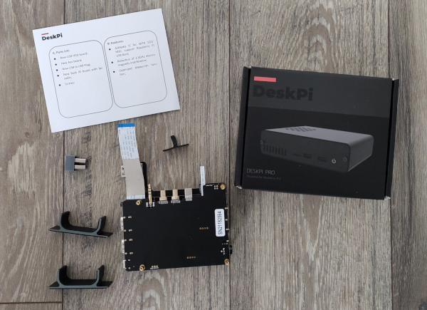
They also provided a set of feet allowing for vertical mounting of the device, which was a nice touch. The USB/SATA bridge chip in use has changed; the original was:
usb 2-1: New USB device found, idVendor=152d, idProduct=0562, bcdDevice= 1.09
usb 2-1: New USB device strings: Mfr=1, Product=2, SerialNumber=3
usb 2-1: Product: RPi_SSD
usb 2-1: Manufacturer: 52Pi
usb 2-1: SerialNumber: DD5641988389F
and the new one is:
usb 2-1: New USB device found, idVendor=174c, idProduct=1153, bcdDevice= 0.01
usb 2-1: New USB device strings: Mfr=2, Product=3, SerialNumber=1
usb 2-1: Product: AS2115
usb 2-1: Manufacturer: ASMedia
usb 2-1: SerialNumber: 00000000000000000000
That s a move from a JMicron 6Gb/s bridge to an ASMedia 3Gb/s bridge. It seems there are compatibility issues with the JMicron that mean the downgrade is the preferred choice. I haven t retried the original SSD I wanted to use (that wasn t detected), but I did wonder if this might have resolved that issue too. Replacing the PCB was easier than the original install; everything was provided pre-assembled and I just had to unscrew the Pi4 and slot it out, then screw it into the new PCB assembly. Everything booted fine without the need for any configuration tweaks. Nice and dull. I ve tried plugging things into the new USB ports and they seem ok so far as well. However I also then ended up pulling in a new backports kernel from Debian (upgrading from 5.9 to 5.10) which resulted in a failure to boot. The kernel and initramfs were loaded fine, but no login prompt ever appeared. Some digging led to the discovery that a change in boot ordering meant USB was not being enabled. The solution is to add reset_raspberrypi to the /etc/initramfs-tools/modules file - that way this module is available in the initramfs, the appropriate pre-USB reset can happen and everything works just fine again. The other niggle with the new kernel was a regular set of errors in the kernel log:
mmc1: Timeout waiting for hardware cmd interrupt.
mmc1: sdhci: ============ SDHCI REGISTER DUMP ===========
and a set of registers afterwards, roughly every 10s or so. This seems to be fallout from an increase in the core clock due to the VC4 driver now being enabled, the fact I have no SD card in the device and a lack of working card-detect line for the MicroSD slot. There s a GitHub issue but I solved it by removing the sdhci_iproc for now - I m not using the wifi so loss of MMC isn t a problem. Credit to DeskPi for how they handled this. I didn t have to do anything and didn t even realise anything was happening until I got the email with my tracking number and a description of what they were sending out in it. Delivery took less than a week. This is a great example of how to handle a product issue - no effort required on the part of the customer.

25 April 2021

Junichi Uekawa: Got a new machine Lenovo ThinkCenter M75s gen2, and installed Debian on it.

Got a new machine Lenovo ThinkCenter M75s gen2, and installed Debian on it. I wanted to try out the ryzen CPU. I haven't used a physical x86-64 Debian desktop machine since I threw away my Athlon 64 machine (dx5150), so that's like 15 years? Since then my main devices were macbooks and virtual machines (on GCE and Sakura) and raspberry pi. I got buster installed just fine. Finding the right keystrokes after boot was challenging because the graphical UI doesn't say anything. For BIOS set up to disable secure boot (F1 to enter set up: I wanted to play with kernel) and finding the keystroke to choose the boot disk (F10 to enter the dialog; I needed to choose the one labeled USB CD drive although I put in a USB SD card reader with installer image). The installation went fine for console, but getting X up was tricky, the support for the graphics (Renoir) part of the chip was added in kernel 5.5. Bullseye was 4.19 and I wasn't too comfortable with just updating the kernel. I ended up going for dist-upgrade to Bullseye. With Bullseye default kernel 5.10, X started without problems. So far I only tried out Emacs.

16 April 2021

Dirk Eddelbuettel: Announcing Introductions to Emacs Speaks Statistics

A new website containing introductory videos and slide decks is now available for your perusal at ess-intro.github.io. It provides a series of introductions to the excellent Emacs Speaks Statistics (ESS) mode for the Emacs editor. This effort started following my little tips, tricks, tools and toys series of short videos and slide decks for the command-line and R, broadly-speaking . Which I had mentioned to friends curious about Emacs, and on the ess-help mailing list. And lo and behold, over the fall and winter sixteen of us came together in one GitHub org and are now proud to present the initial batch of videos about first steps, installing, using with spaceemacs, customizing, and org-mode with ESS. More may hopefully fellow, the group is open and you too can join: see the main repo and its wiki. This is in fact the initial announcement post, so it is flattering that we have already received over 350 views, four comments and twenty-one likes. We hope it proves to be a useful starting point for some of you. The Emacs editor is quite uniquely powerful, and coupled with ESS makes for a rather nice environment for programming with data, or analysing, visualising, exploring, data. But we are not zealots: there are many editors and environments under the sun, and most people are perfectly happy with their choice, which is wonderful. We also like ours, and sometimes someone asks tell me more or how do I start . We hope this series satisifies this initial curiousity and takes it from here. With that, my thanks to Fr d ric, Alex, Tyler and Greg for the initial batch, and for everybody else in the org who chipped in with comments and suggestion. We hope it grows from here, so happy Emacsing with R from us!

21 February 2021

Matthew Garrett: Making hibernation work under Linux Lockdown

Linux draws a distinction between code running in kernel (kernel space) and applications running in userland (user space). This is enforced at the hardware level - in x86-speak[1], kernel space code runs in ring 0 and user space code runs in ring 3[2]. If you're running in ring 3 and you attempt to touch memory that's only accessible in ring 0, the hardware will raise a fault. No matter how privileged your ring 3 code, you don't get to touch ring 0.

Kind of. In theory. Traditionally this wasn't well enforced. At the most basic level, since root can load kernel modules, you could just build a kernel module that performed any kernel modifications you wanted and then have root load it. Technically user space code wasn't modifying kernel space code, but the difference was pretty semantic rather than useful. But it got worse - root could also map memory ranges belonging to PCI devices[3], and if the device could perform DMA you could just ask the device to overwrite bits of the kernel[4]. Or root could modify special CPU registers ("Model Specific Registers", or MSRs) that alter CPU behaviour via the /dev/msr interface, and compromise the kernel boundary that way.

It turns out that there were a number of ways root was effectively equivalent to ring 0, and the boundary was more about reliability (ie, a process running as root that ends up misbehaving should still only be able to crash itself rather than taking down the kernel with it) than security. After all, if you were root you could just replace the on-disk kernel with a backdoored one and reboot. Going deeper, you could replace the bootloader with one that automatically injected backdoors into a legitimate kernel image. We didn't have any way to prevent this sort of thing, so attempting to harden the root/kernel boundary wasn't especially interesting.

In 2012 Microsoft started requiring vendors ship systems with UEFI Secure Boot, a firmware feature that allowed[5] systems to refuse to boot anything without an appropriate signature. This not only enabled the creation of a system that drew a strong boundary between root and kernel, it arguably required one - what's the point of restricting what the firmware will stick in ring 0 if root can just throw more code in there afterwards? What ended up as the Lockdown Linux Security Module provides the tooling for this, blocking userspace interfaces that can be used to modify the kernel and enforcing that any modules have a trusted signature.

But that comes at something of a cost. Most of the features that Lockdown blocks are fairly niche, so the direct impact of having it enabled is small. Except that it also blocks hibernation[6], and it turns out some people were using that. The obvious question is "what does hibernation have to do with keeping root out of kernel space", and the answer is a little convoluted and is tied into how Linux implements hibernation. Basically, Linux saves system state into the swap partition and modifies the header to indicate that there's a hibernation image there instead of swap. On the next boot, the kernel sees the header indicating that it's a hibernation image, copies the contents of the swap partition back into RAM, and then jumps back into the old kernel code. What ensures that the hibernation image was actually written out by the kernel? Absolutely nothing, which means a motivated attacker with root access could turn off swap, write a hibernation image to the swap partition themselves, and then reboot. The kernel would happily resume into the attacker's image, giving the attacker control over what gets copied back into kernel space.

This is annoying, because normally when we think about attacks on swap we mitigate it by requiring an encrypted swap partition. But in this case, our attacker is root, and so already has access to the plaintext version of the swap partition. Disk encryption doesn't save us here. We need some way to verify that the hibernation image was written out by the kernel, not by root. And thankfully we have some tools for that.

Trusted Platform Modules (TPMs) are cryptographic coprocessors[7] capable of doing things like generating encryption keys and then encrypting things with them. You can ask a TPM to encrypt something with a key that's tied to that specific TPM - the OS has no access to the decryption key, and nor does any other TPM. So we can have the kernel generate an encryption key, encrypt part of the hibernation image with it, and then have the TPM encrypt it. We store the encrypted copy of the key in the hibernation image as well. On resume, the kernel reads the encrypted copy of the key, passes it to the TPM, gets the decrypted copy back and is able to verify the hibernation image.

That's great! Except root can do exactly the same thing. This tells us the hibernation image was generated on this machine, but doesn't tell us that it was done by the kernel. We need some way to be able to differentiate between keys that were generated in kernel and ones that were generated in userland. TPMs have the concept of "localities" (effectively privilege levels) that would be perfect for this. Userland is only able to access locality 0, so the kernel could simply use locality 1 to encrypt the key. Unfortunately, despite trying pretty hard, I've been unable to get localities to work. The motherboard chipset on my test machines simply doesn't forward any accesses to the TPM unless they're for locality 0. I needed another approach.

TPMs have a set of Platform Configuration Registers (PCRs), intended for keeping a record of system state. The OS isn't able to modify the PCRs directly. Instead, the OS provides a cryptographic hash of some material to the TPM. The TPM takes the existing PCR value, appends the new hash to that, and then stores the hash of the combination in the PCR - a process called "extension". This means that the new value of the TPM depends not only on the value of the new data, it depends on the previous value of the PCR - and, in turn, that previous value depended on its previous value, and so on. The only way to get to a specific PCR value is to either (a) break the hash algorithm, or (b) perform exactly the same sequence of writes. On system reset the PCRs go back to a known value, and the entire process starts again.

Some PCRs are different. PCR 23, for example, can be reset back to its original value without resetting the system. We can make use of that. The first thing we need to do is to prevent userland from being able to reset or extend PCR 23 itself. All TPM accesses go through the kernel, so this is a simple matter of parsing the write before it's sent to the TPM and returning an error if it's a sensitive command that would touch PCR 23. We now know that any change in PCR 23's state will be restricted to the kernel.

When we encrypt material with the TPM, we can ask it to record the PCR state. This is given back to us as metadata accompanying the encrypted secret. Along with the metadata is an additional signature created by the TPM, which can be used to prove that the metadata is both legitimate and associated with this specific encrypted data. In our case, that means we know what the value of PCR 23 was when we encrypted the key. That means that if we simply extend PCR 23 with a known value in-kernel before encrypting our key, we can look at the value of PCR 23 in the metadata. If it matches, the key was encrypted by the kernel - userland can create its own key, but it has no way to extend PCR 23 to the appropriate value first. We now know that the key was generated by the kernel.

But what if the attacker is able to gain access to the encrypted key? Let's say a kernel bug is hit that prevents hibernation from resuming, and you boot back up without wiping the hibernation image. Root can then read the key from the partition, ask the TPM to decrypt it, and then use that to create a new hibernation image. We probably want to prevent that as well. Fortunately, when you ask the TPM to encrypt something, you can ask that the TPM only decrypt it if the PCRs have specific values. "Sealing" material to the TPM in this way allows you to block decryption if the system isn't in the desired state. So, we define a policy that says that PCR 23 must have the same value at resume as it did on hibernation. On resume, the kernel resets PCR 23, extends it to the same value it did during hibernation, and then attempts to decrypt the key. Afterwards, it resets PCR 23 back to the initial value. Even if an attacker gains access to the encrypted copy of the key, the TPM will refuse to decrypt it.

And that's what this patchset implements. There's one fairly significant flaw at the moment, which is simply that an attacker can just reboot into an older kernel that doesn't implement the PCR 23 blocking and set up state by hand. Fortunately, this can be avoided using another aspect of the boot process. When you boot something via UEFI Secure Boot, the signing key used to verify the booted code is measured into PCR 7 by the system firmware. In the Linux world, the Shim bootloader then measures any additional keys that are used. By either using a new key to tag kernels that have support for the PCR 23 restrictions, or by embedding some additional metadata in the kernel that indicates the presence of this feature and measuring that, we can have a PCR 7 value that verifies that the PCR 23 restrictions are present. We then seal the key to PCR 7 as well as PCR 23, and if an attacker boots into a kernel that doesn't have this feature the PCR 7 value will be different and the TPM will refuse to decrypt the secret.

While there's a whole bunch of complexity here, the process should be entirely transparent to the user. The current implementation requires a TPM 2, and I'm not certain whether TPM 1.2 provides all the features necessary to do this properly - if so, extending it shouldn't be hard, but also all systems shipped in the past few years should have a TPM 2, so that's going to depend on whether there's sufficient interest to justify the work. And we're also at the early days of review, so there's always the risk that I've missed something obvious and there are terrible holes in this. And, well, given that it took almost 8 years to get the Lockdown patchset into mainline, let's not assume that I'm good at landing security code.

[1] Other architectures use different terminology here, such as "supervisor" and "user" mode, but it's broadly equivalent
[2] In theory rings 1 and 2 would allow you to run drivers with privileges somewhere between full kernel access and userland applications, but in reality we just don't talk about them in polite company
[3] This is how graphics worked in Linux before kernel modesetting turned up. XFree86 would just map your GPU's registers into userland and poke them directly. This was not a huge win for stability
[4] IOMMUs can help you here, by restricting the memory PCI devices can DMA to or from. The kernel then gets to allocate ranges for device buffers and configure the IOMMU such that the device can't DMA to anything else. Except that region of memory may still contain sensitive material such as function pointers, and attacks like this can still cause you problems as a result.
[5] This describes why I'm using "allowed" rather than "required" here
[6] Saving the system state to disk and powering down the platform entirely - significantly slower than suspending the system while keeping state in RAM, but also resilient against the system losing power.
[7] With some handwaving around "coprocessor". TPMs can't be part of the OS or the system firmware, but they don't technically need to be an independent component. Intel have a TPM implementation that runs on the Management Engine, a separate processor built into the motherboard chipset. AMD have one that runs on the Platform Security Processor, a small ARM core built into their CPU. Various ARM implementations run a TPM in Trustzone, a special CPU mode that (in theory) is able to access resources that are entirely blocked off from anything running in the OS, kernel or otherwise.

comment count unavailable comments

18 February 2021

Jonathan McDowell: Hacking and Bricking the EE Opsrey 2 Mini

I ve mentioned in the past my twisted EE network setup from when I moved in to my current house. The 4GEE WiFi Mini (also known as the EE Osprey 2 Mini or the EE40VB, and actually a rebadged Alcatel Y853VB) has been sitting unused since then, so I figured I d see about trying to get a shell on it. TL;DR: Of course it s running Linux, there s a couple of test points internally which bring out the serial console, but after finding those and logging in I discovered it s running ADB on port 5555 quite happily available without authentication both via wifi and the USB port. So if you have physical or local network access, instant root shell. Well done, folks. And then I bricked it before I could do anything more interesting. There s a lack of information about this device out there - most of the links I can find are around removing the SIM lock - so I thought I d document the pieces I found just in case anyone else is trying to figure it out. It s based around a Qualcomm MDM9607 SoC, paired with 64M RAM and 256M NAND flash. Wifi is via an RTL8192ES. Kernel is 3.18.20. Busybox is v1.23.1. It s running dnsmasq but I didn t grab the version. Of course there s no source or offer of source provided. Taking it apart is fairly easy. There s a single screw to remove, just beside the SIM slot. The coloured rim can then be carefully pried away from the back, revealing the battery. There are then 4 screws in the corners which need removed in order to be able to lift out the actual PCB and gain access to the serial console test points. EE40VB PCB serial console test points My mistake was going poking around trying to figure out where the updates are downloaded from - I know I m running a slightly older release than what s current, and the device can do an automatic download + update. Top tip; don t run Jrdrecovery. It ll error on finding /cache/update.zip and wipe the main partition anyway. That ll leave you in a boot loop where the device boots the recovery partition which tries to install /cache/update.zip which of course still doesn t exist. So. Where next? First, I need to get the device into a state where I can actually do something other than watch it boot into recovery, fail to flash and reboot. Best guess at present is to try and get it to enter the Qualcomm EDL (Emergency Download) mode. That might be possible with a custom USB cable that grounds D+ on boot. Alternatively I need to probe some of the other test points on the PCB and see if grounding any of those helps enter EDL mode. I then need a suitable firehose OEM-signed programmer image. And then I need to actually get hold of a proper EE40VB firmware image, either via one of the OTA update files or possibly via an Alcatel ADSU image (though no idea how to get hold of one, other than by posting to a random GSM device forum and hoping for the kindness of strangers). More updates if/when I make progress
Qualcomm bootloader log
Format: Log Type - Time(microsec) - Message - Optional Info
Log Type: B - Since Boot(Power On Reset),  D - Delta,  S - Statistic
S - QC_IMAGE_VERSION_STRING=BOOT.BF.3.1.2-00053
S - IMAGE_VARIANT_STRING=LAATANAZA
S - OEM_IMAGE_VERSION_STRING=linux3
S - Boot Config, 0x000002e1
B -    105194 - SBL1, Start
D -     61885 - QSEE Image Loaded, Delta - (451964 Bytes)
D -     30286 - RPM Image Loaded, Delta - (151152 Bytes)
B -    459330 - Roger:boot_jrd_oem_main
B -    461526 - Welcome to key_check_poweron!!!
B -    466436 - REG0x00, rc=47
B -    469120 - REG0x01, rc=1f
B -    472018 - REG0x02, rc=1c
B -    474885 - REG0x03, rc=47
B -    477782 - REG0x04, rc=b2
B -    480558 - REG0x05, rc=
B -    483272 - REG0x06, rc=9e
B -    486139 - REG0x07, rc=
B -    488854 - REG0x08, rc=a4
B -    491721 - REG0x09, rc=80
B -    494130 - bq24295_probe: vflt/vsys/vprechg=0mV/0mV/0mV, tprechg/tfastchg=0Min/0Min, [0C, 0C]
B -    511546 - come to calculate vol and temperature!!
B -    511637 - ##############battery_core_convert_vntc: NTC_voltage=1785690
B -    517280 - battery_core_convert_vntc: <-44C, 1785690uV>, present=0
B -    529358 - bq24295_set_current_limit: setting=0mA, mode=-1, input/fastchg/prechg/termchg=-1mA/0mA/0mA/0mA
B -    534360 - bq24295_set_charge_current, rc=0,reg_val=0,i=0
B -    539636 - bq24295_enable_charge: setting=0, chg_enable=-1, otg_enable=0
B -    546072 - bq24295_enable_charging: enable_charging=0
B -    552172 - bq24295_set_current_limit: setting=0mA, mode=-1, input/fastchg/prechg/termchg=-1mA/0mA/0mA/0mA
B -    561566 - bq24295_set_charge_current, rc=0,reg_val=0,i=0
B -    567056 - bq24295_enable_charge: setting=0, chg_enable=0, otg_enable=0
B -    579286 - come to calculate vol and temperature!!
B -    579378 - ##############battery_core_convert_vntc: NTC_voltage=1785777
B -    585539 - battery_core_convert_vntc: <-44C, 1785777uV>, present=0
B -    597617 - charge_main: battery is plugout!!
B -    597678 - Welcome to pca955x_probe!!!
B -    601063 - pca955x_probe: PCA955X probed successfully!
D -     27511 - APPSBL Image Loaded, Delta - (179348 Bytes)
B -    633271 - QSEE Execution, Start
D -       213 - QSEE Execution, Delta
B -    638944 - >>>>>>>>>>>>>>>>>>>>>>>>>>>>>>>>>Start writting JRD RECOVERY BOOT
B -    650107 - >>>>>>>>>>>>>>>>>>>>>>>>>>>>>>>>>Start writting  RECOVERY BOOT
B -    653218 - >>>>>>>>>>>>>>>>>>>>>>>>>>>>>>>>>read_buf[0] == 0
B -    659044 - SBL1, End
D -    556137 - SBL1, Delta
S - Throughput, 2000 KB/s  (782884 Bytes,  278155 us)
S - DDR Frequency, 240 MHz
littlekernel aboot log
Android Bootloader - UART_DM Initialized!!!
[0] welcome to lk
[0] SCM call: 0x2000601 failed with :fffffffc
[0] Failed to initialize SCM
[10] platform_init()
[10] target_init()
[10] smem ptable found: ver: 4 len: 17
[10] ERROR: No devinfo partition found
[10] Neither 'config' nor 'frp' partition found
[30] voltage of NTC  is 1789872!
[30] voltage of BAT  is 3179553!
[30] usb present is 1!
[30] Loading (boot) image (4171776): start
[530] Loading (boot) image (4171776): done
[540] DTB Total entry: 25, DTB version: 3
[540] Using DTB entry 0x00000129/00010000/0x00000008/0 for device 0x00000129/00010000/0x00010008/0
[560] JRD_CHG_OFF_FEATURE!
[560] come to jrd_target_pause_for_battery_charge!
[570] power_on_status.hard_reset = 0x0
[570] power_on_status.smpl = 0x0
[570] power_on_status.rtc = 0x0
[580] power_on_status.dc_chg = 0x0
[580] power_on_status.usb_chg = 0x0
[580] power_on_status.pon1 = 0x1
[590] power_on_status.cblpwr = 0x0
[590] power_on_status.kpdpwr = 0x0
[590] power_on_status.bugflag = 0x0
[590] cmdline: noinitrd  rw console=ttyHSL0,115200,n8 androidboot.hardware=qcom ehci-hcd.park=3 msm_rtb.filter=0x37 lpm_levels.sleep_disabled=1  earlycon=msm_hsl_uart,0x78b3000  androidboot.serialno=7e6ba58c androidboot.baseband=msm rootfstype=ubifs rootflags=b
[620] Updating device tree: start
[720] Updating device tree: done
[720] booting linux @ 0x80008000, ramdisk @ 0x80008000 (0), tags/device tree @ 0x81e00000
Linux kernel console boot log
[    0.000000] Booting Linux on physical CPU 0x0
[    0.000000] Linux version 3.18.20 (linux3@linux3) (gcc version 4.9.2 (GCC) ) #1 PREEMPT Thu Aug 10 11:57:07 CST 2017
[    0.000000] CPU: ARMv7 Processor [410fc075] revision 5 (ARMv7), cr=10c53c7d
[    0.000000] CPU: PIPT / VIPT nonaliasing data cache, VIPT aliasing instruction cache
[    0.000000] Machine model: Qualcomm Technologies, Inc. MDM 9607 MTP
[    0.000000] Early serial console at I/O port 0x0 (options '')
[    0.000000] bootconsole [uart0] enabled
[    0.000000] Reserved memory: reserved region for node 'modem_adsp_region@0': base 0x82a00000, size 56 MiB
[    0.000000] Reserved memory: reserved region for node 'external_image_region@0': base 0x87c00000, size 4 MiB
[    0.000000] Removed memory: created DMA memory pool at 0x82a00000, size 56 MiB
[    0.000000] Reserved memory: initialized node modem_adsp_region@0, compatible id removed-dma-pool
[    0.000000] Removed memory: created DMA memory pool at 0x87c00000, size 4 MiB
[    0.000000] Reserved memory: initialized node external_image_region@0, compatible id removed-dma-pool
[    0.000000] cma: Reserved 4 MiB at 0x87800000
[    0.000000] Memory policy: Data cache writeback
[    0.000000] CPU: All CPU(s) started in SVC mode.
[    0.000000] Built 1 zonelists in Zone order, mobility grouping on.  Total pages: 17152
[    0.000000] Kernel command line: noinitrd  rw console=ttyHSL0,115200,n8 androidboot.hardware=qcom ehci-hcd.park=3 msm_rtb.filter=0x37 lpm_levels.sleep_disabled=1  earlycon=msm_hsl_uart,0x78b3000  androidboot.serialno=7e6ba58c androidboot.baseband=msm rootfstype=ubifs rootflags=bulk_read root=ubi0:rootfs ubi.mtd=16
[    0.000000] PID hash table entries: 512 (order: -1, 2048 bytes)
[    0.000000] Dentry cache hash table entries: 16384 (order: 4, 65536 bytes)
[    0.000000] Inode-cache hash table entries: 8192 (order: 3, 32768 bytes)
[    0.000000] Memory: 54792K/69632K available (5830K kernel code, 399K rwdata, 2228K rodata, 276K init, 830K bss, 14840K reserved)
[    0.000000] Virtual kernel memory layout:
[    0.000000]     vector  : 0xffff0000 - 0xffff1000   (   4 kB)
[    0.000000]     fixmap  : 0xffc00000 - 0xfff00000   (3072 kB)
[    0.000000]     vmalloc : 0xc8800000 - 0xff000000   ( 872 MB)
[    0.000000]     lowmem  : 0xc0000000 - 0xc8000000   ( 128 MB)
[    0.000000]     modules : 0xbf000000 - 0xc0000000   (  16 MB)
[    0.000000]       .text : 0xc0008000 - 0xc07e6c38   (8060 kB)
[    0.000000]       .init : 0xc07e7000 - 0xc082c000   ( 276 kB)
[    0.000000]       .data : 0xc082c000 - 0xc088fdc0   ( 400 kB)
[    0.000000]        .bss : 0xc088fe84 - 0xc095f798   ( 831 kB)
[    0.000000] SLUB: HWalign=64, Order=0-3, MinObjects=0, CPUs=1, Nodes=1
[    0.000000] Preemptible hierarchical RCU implementation.
[    0.000000] NR_IRQS:16 nr_irqs:16 16
[    0.000000] GIC CPU mask not found - kernel will fail to boot.
[    0.000000] GIC CPU mask not found - kernel will fail to boot.
[    0.000000] mpm_init_irq_domain(): Cannot find irq controller for qcom,gpio-parent
[    0.000000] MPM 1 irq mapping errored -517
[    0.000000] Architected mmio timer(s) running at 19.20MHz (virt).
[    0.000011] sched_clock: 56 bits at 19MHz, resolution 52ns, wraps every 3579139424256ns
[    0.007975] Switching to timer-based delay loop, resolution 52ns
[    0.013969] Switched to clocksource arch_mem_counter
[    0.019687] Console: colour dummy device 80x30
[    0.023344] Calibrating delay loop (skipped), value calculated using timer frequency.. 38.40 BogoMIPS (lpj=192000)
[    0.033666] pid_max: default: 32768 minimum: 301
[    0.038411] Mount-cache hash table entries: 1024 (order: 0, 4096 bytes)
[    0.044902] Mountpoint-cache hash table entries: 1024 (order: 0, 4096 bytes)
[    0.052445] CPU: Testing write buffer coherency: ok
[    0.057057] Setting up static identity map for 0x8058aac8 - 0x8058ab20
[    0.064242]
[    0.064242] **********************************************************
[    0.071251] **   NOTICE NOTICE NOTICE NOTICE NOTICE NOTICE NOTICE   **
[    0.077817] **                                                      **
[    0.084302] ** trace_printk() being used. Allocating extra memory.  **
[    0.090781] **                                                      **
[    0.097320] ** This means that this is a DEBUG kernel and it is     **
[    0.103802] ** unsafe for produciton use.                           **
[    0.110339] **                                                      **
[    0.116850] ** If you see this message and you are not debugging    **
[    0.123333] ** the kernel, report this immediately to your vendor!  **
[    0.129870] **                                                      **
[    0.136380] **   NOTICE NOTICE NOTICE NOTICE NOTICE NOTICE NOTICE   **
[    0.142865] **********************************************************
[    0.150225] MSM Memory Dump base table set up
[    0.153739] MSM Memory Dump apps data table set up
[    0.168125] VFP support v0.3: implementor 41 architecture 2 part 30 variant 7 rev 5
[    0.176332] pinctrl core: initialized pinctrl subsystem
[    0.180930] regulator-dummy: no parameters
[    0.215338] NET: Registered protocol family 16
[    0.220475] DMA: preallocated 256 KiB pool for atomic coherent allocations
[    0.284034] cpuidle: using governor ladder
[    0.314026] cpuidle: using governor menu
[    0.344024] cpuidle: using governor qcom
[    0.355452] msm_watchdog b017000.qcom,wdt: wdog absent resource not present
[    0.361656] msm_watchdog b017000.qcom,wdt: MSM Watchdog Initialized
[    0.371373] irq: no irq domain found for /soc/pinctrl@1000000 !
[    0.381268] spmi_pmic_arb 200f000.qcom,spmi: PMIC Arb Version-2 0x20010000
[    0.389733] platform 4080000.qcom,mss: assigned reserved memory node modem_adsp_region@0
[    0.397409] mem_acc_corner: 0 <--> 0 mV
[    0.401937] hw-breakpoint: found 5 (+1 reserved) breakpoint and 4 watchpoint registers.
[    0.408966] hw-breakpoint: maximum watchpoint size is 8 bytes.
[    0.416287] __of_mpm_init(): MPM driver mapping exists
[    0.420940] msm_rpm_glink_dt_parse: qcom,rpm-glink compatible not matches
[    0.427235] msm_rpm_dev_probe: APSS-RPM communication over SMD
[    0.432977] smd_open() before smd_init()
[    0.437544] msm_mpm_dev_probe(): Cannot get clk resource for XO: -517
[    0.445730] smd_channel_probe_now: allocation table not initialized
[    0.453100] mdm9607_s1: 1050 <--> 1350 mV at 1225 mV normal idle
[    0.458566] spm_regulator_probe: name=mdm9607_s1, range=LV, voltage=1225000 uV, mode=AUTO, step rate=4800 uV/us
[    0.468817] cpr_efuse_init: apc_corner: efuse_addr = 0x000a4000 (len=0x1000)
[    0.475353] cpr_read_fuse_revision: apc_corner: fuse revision = 2
[    0.481345] cpr_parse_speed_bin_fuse: apc_corner: [row: 37]: 0x79e8bd327e6ba58c, speed_bits = 4
[    0.490124] cpr_pvs_init: apc_corner: pvs voltage: [1050000 1100000 1275000] uV
[    0.497342] cpr_pvs_init: apc_corner: ceiling voltage: [1050000 1225000 1350000] uV
[    0.504979] cpr_pvs_init: apc_corner: floor voltage: [1050000 1050000 1150000] uV
[    0.513125] i2c-msm-v2 78b8000.i2c: probing driver i2c-msm-v2
[    0.518335] i2c-msm-v2 78b8000.i2c: error on clk_get(core_clk):-517
[    0.524478] i2c-msm-v2 78b8000.i2c: error probe() failed with err:-517
[    0.531111] i2c-msm-v2 78b7000.i2c: probing driver i2c-msm-v2
[    0.536788] i2c-msm-v2 78b7000.i2c: error on clk_get(core_clk):-517
[    0.542886] i2c-msm-v2 78b7000.i2c: error probe() failed with err:-517
[    0.549618] i2c-msm-v2 78b9000.i2c: probing driver i2c-msm-v2
[    0.555202] i2c-msm-v2 78b9000.i2c: error on clk_get(core_clk):-517
[    0.561374] i2c-msm-v2 78b9000.i2c: error probe() failed with err:-517
[    0.570613] msm-thermal soc:qcom,msm-thermal: msm_thermal:Failed reading node=/soc/qcom,msm-thermal, key=qcom,core-limit-temp. err=-22. KTM continues
[    0.583049] msm-thermal soc:qcom,msm-thermal: probe_therm_reset:Failed reading node=/soc/qcom,msm-thermal, key=qcom,therm-reset-temp err=-22. KTM continues
[    0.596926] msm_thermal:msm_thermal_dev_probe Failed reading node=/soc/qcom,msm-thermal, key=qcom,online-hotplug-core. err:-517
[    0.609370] sps:sps is ready.
[    0.613137] msm_rpm_glink_dt_parse: qcom,rpm-glink compatible not matches
[    0.619020] msm_rpm_dev_probe: APSS-RPM communication over SMD
[    0.625773] mdm9607_s2: 750 <--> 1275 mV at 750 mV normal idle
[    0.631584] mdm9607_s3_level: 0 <--> 0 mV at 0 mV normal idle
[    0.637085] mdm9607_s3_level_ao: 0 <--> 0 mV at 0 mV normal idle
[    0.643092] mdm9607_s3_floor_level: 0 <--> 0 mV at 0 mV normal idle
[    0.649512] mdm9607_s3_level_so: 0 <--> 0 mV at 0 mV normal idle
[    0.655750] mdm9607_s4: 1800 <--> 1950 mV at 1800 mV normal idle
[    0.661791] mdm9607_l1: 1250 mV normal idle
[    0.666090] mdm9607_l2: 1800 mV normal idle
[    0.670276] mdm9607_l3: 1800 mV normal idle
[    0.674541] mdm9607_l4: 3075 mV normal idle
[    0.678743] mdm9607_l5: 1700 <--> 3050 mV at 1700 mV normal idle
[    0.684904] mdm9607_l6: 1700 <--> 3050 mV at 1700 mV normal idle
[    0.690892] mdm9607_l7: 1700 <--> 1900 mV at 1700 mV normal idle
[    0.697036] mdm9607_l8: 1800 mV normal idle
[    0.701238] mdm9607_l9: 1200 <--> 1250 mV at 1200 mV normal idle
[    0.707367] mdm9607_l10: 1050 mV normal idle
[    0.711662] mdm9607_l11: 1800 mV normal idle
[    0.716089] mdm9607_l12_level: 0 <--> 0 mV at 0 mV normal idle
[    0.721717] mdm9607_l12_level_ao: 0 <--> 0 mV at 0 mV normal idle
[    0.727946] mdm9607_l12_level_so: 0 <--> 0 mV at 0 mV normal idle
[    0.734099] mdm9607_l12_floor_lebel: 0 <--> 0 mV at 0 mV normal idle
[    0.740706] mdm9607_l13: 1800 <--> 2850 mV at 2850 mV normal idle
[    0.746883] mdm9607_l14: 2650 <--> 3000 mV at 2650 mV normal idle
[    0.752515] msm_mpm_dev_probe(): Cannot get clk resource for XO: -517
[    0.759036] cpr_efuse_init: apc_corner: efuse_addr = 0x000a4000 (len=0x1000)
[    0.765807] cpr_read_fuse_revision: apc_corner: fuse revision = 2
[    0.771809] cpr_parse_speed_bin_fuse: apc_corner: [row: 37]: 0x79e8bd327e6ba58c, speed_bits = 4
[    0.780586] cpr_pvs_init: apc_corner: pvs voltage: [1050000 1100000 1275000] uV
[    0.787808] cpr_pvs_init: apc_corner: ceiling voltage: [1050000 1225000 1350000] uV
[    0.795443] cpr_pvs_init: apc_corner: floor voltage: [1050000 1050000 1150000] uV
[    0.803094] cpr_init_cpr_parameters: apc_corner: up threshold = 2, down threshold = 3
[    0.810752] cpr_init_cpr_parameters: apc_corner: CPR is enabled by default.
[    0.817687] cpr_init_cpr_efuse: apc_corner: [row:65] = 0x15000277277383
[    0.824272] cpr_init_cpr_efuse: apc_corner: CPR disable fuse = 0
[    0.830225] cpr_init_cpr_efuse: apc_corner: Corner[1]: ro_sel = 0, target quot = 631
[    0.837976] cpr_init_cpr_efuse: apc_corner: Corner[2]: ro_sel = 0, target quot = 631
[    0.845703] cpr_init_cpr_efuse: apc_corner: Corner[3]: ro_sel = 0, target quot = 899
[    0.853592] cpr_config: apc_corner: Timer count: 0x17700 (for 5000 us)
[    0.860426] apc_corner: 0 <--> 0 mV
[    0.864044] i2c-msm-v2 78b8000.i2c: probing driver i2c-msm-v2
[    0.869261] i2c-msm-v2 78b8000.i2c: error on clk_get(core_clk):-517
[    0.875492] i2c-msm-v2 78b8000.i2c: error probe() failed with err:-517
[    0.882225] i2c-msm-v2 78b7000.i2c: probing driver i2c-msm-v2
[    0.887775] i2c-msm-v2 78b7000.i2c: error on clk_get(core_clk):-517
[    0.893941] i2c-msm-v2 78b7000.i2c: error probe() failed with err:-517
[    0.900719] i2c-msm-v2 78b9000.i2c: probing driver i2c-msm-v2
[    0.906256] i2c-msm-v2 78b9000.i2c: error on clk_get(core_clk):-517
[    0.912430] i2c-msm-v2 78b9000.i2c: error probe() failed with err:-517
[    0.919472] msm-thermal soc:qcom,msm-thermal: msm_thermal:Failed reading node=/soc/qcom,msm-thermal, key=qcom,core-limit-temp. err=-22. KTM continues
[    0.932372] msm-thermal soc:qcom,msm-thermal: probe_therm_reset:Failed reading node=/soc/qcom,msm-thermal,
key=qcom,therm-reset-temp err=-22. KTM continues
[    0.946361] msm_thermal:get_kernel_cluster_info CPU0 topology not initialized.
[    0.953824] cpu cpu0: dev_pm_opp_get_opp_count: device OPP not found (-19)
[    0.960300] msm_thermal:get_cpu_freq_plan_len Error reading CPU0 freq table len. error:-19
[    0.968533] msm_thermal:vdd_restriction_reg_init Defer vdd rstr freq init.
[    0.975846] cpu cpu0: dev_pm_opp_get_opp_count: device OPP not found (-19)
[    0.982219] msm_thermal:get_cpu_freq_plan_len Error reading CPU0 freq table len. error:-19
[    0.991378] cpu cpu0: dev_pm_opp_get_opp_count: device OPP not found (-19)
[    0.997544] msm_thermal:get_cpu_freq_plan_len Error reading CPU0 freq table len. error:-19
[    1.013642] qcom,gcc-mdm9607 1800000.qcom,gcc: Registered GCC clocks
[    1.019451] clock-a7 b010008.qcom,clock-a7: Speed bin: 4 PVS Version: 0
[    1.025693] a7ssmux: set OPP pair(400000000 Hz: 1 uV) on cpu0
[    1.031314] a7ssmux: set OPP pair(1305600000 Hz: 7 uV) on cpu0
[    1.038805] i2c-msm-v2 78b8000.i2c: probing driver i2c-msm-v2
[    1.043587] AXI: msm_bus_scale_register_client(): msm_bus_scale_register_client: Bus driver not ready.
[    1.052935] i2c-msm-v2 78b8000.i2c: msm_bus_scale_register_client(mstr-id:86):0 (not a problem)
[    1.062006] irq: no irq domain found for /soc/wcd9xxx-irq !
[    1.069884] i2c-msm-v2 78b7000.i2c: probing driver i2c-msm-v2
[    1.074814] AXI: msm_bus_scale_register_client(): msm_bus_scale_register_client: Bus driver not ready.
[    1.083716] i2c-msm-v2 78b7000.i2c: msm_bus_scale_register_client(mstr-id:86):0 (not a problem)
[    1.093850] i2c-msm-v2 78b9000.i2c: probing driver i2c-msm-v2
[    1.098889] AXI: msm_bus_scale_register_client(): msm_bus_scale_register_client: Bus driver not ready.
[    1.107779] i2c-msm-v2 78b9000.i2c: msm_bus_scale_register_client(mstr-id:86):0 (not a problem)
[    1.167871] KPI: Bootloader start count = 24097
[    1.171364] KPI: Bootloader end count = 48481
[    1.175855] KPI: Bootloader display count = 3884474147
[    1.180825] KPI: Bootloader load kernel count = 16420
[    1.185905] KPI: Kernel MPM timestamp = 105728
[    1.190286] KPI: Kernel MPM Clock frequency = 32768
[    1.195209] socinfo_print: v0.10, id=297, ver=1.0, raw_id=72, raw_ver=0, hw_plat=8, hw_plat_ver=65536
[    1.195209]  accessory_chip=0, hw_plat_subtype=0, pmic_model=65539, pmic_die_revision=131074 foundry_id=0 serial_number=2120983948
[    1.216731] sdcard_ext_vreg: no parameters
[    1.220555] rome_vreg: no parameters
[    1.224133] emac_lan_vreg: no parameters
[    1.228177] usbcore: registered new interface driver usbfs
[    1.233156] usbcore: registered new interface driver hub
[    1.238578] usbcore: registered new device driver usb
[    1.244507] cpufreq: driver msm up and running
[    1.248425] ION heap system created
[    1.251895] msm_bus_fabric_init_driver
[    1.262563] qcom,qpnp-power-on qpnp-power-on-c7303800: PMIC@SID0 Power-on reason: Triggered from PON1 (secondary PMIC) and 'cold' boot
[    1.273747] qcom,qpnp-power-on qpnp-power-on-c7303800: PMIC@SID0: Power-off reason: Triggered from UVLO (Under Voltage Lock Out)
[    1.285430] input: qpnp_pon as /devices/virtual/input/input0
[    1.291246] PMIC@SID0: PM8019 v2.2 options: 3, 2, 2, 2
[    1.296706] Advanced Linux Sound Architecture Driver Initialized.
[    1.302493] Add group failed
[    1.305291] cfg80211: Calling CRDA to update world regulatory domain
[    1.311216] cfg80211: World regulatory domain updated:
[    1.317109] Switched to clocksource arch_mem_counter
[    1.334091] cfg80211:  DFS Master region: unset
[    1.337418] cfg80211:   (start_freq - end_freq @ bandwidth), (max_antenna_gain, max_eirp), (dfs_cac_time)
[    1.354087] cfg80211:   (2402000 KHz - 2472000 KHz @ 40000 KHz), (N/A, 2000 mBm), (N/A)
[    1.361055] cfg80211:   (2457000 KHz - 2482000 KHz @ 40000 KHz), (N/A, 2000 mBm), (N/A)
[    1.370545] NET: Registered protocol family 2
[    1.374082] cfg80211:   (2474000 KHz - 2494000 KHz @ 20000 KHz), (N/A, 2000 mBm), (N/A)
[    1.381851] cfg80211:   (5170000 KHz - 5250000 KHz @ 80000 KHz), (N/A, 2000 mBm), (N/A)
[    1.389876] cfg80211:   (5250000 KHz - 5330000 KHz @ 80000 KHz), (N/A, 2000 mBm), (N/A)
[    1.397857] cfg80211:   (5490000 KHz - 5710000 KHz @ 80000 KHz), (N/A, 2000 mBm), (N/A)
[    1.405841] cfg80211:   (5735000 KHz - 5835000 KHz @ 80000 KHz), (N/A, 2000 mBm), (N/A)
[    1.413795] cfg80211:   (57240000 KHz - 63720000 KHz @ 2160000 KHz), (N/A, 0 mBm), (N/A)
[    1.422355] TCP established hash table entries: 1024 (order: 0, 4096 bytes)
[    1.428921] TCP bind hash table entries: 1024 (order: 0, 4096 bytes)
[    1.435192] TCP: Hash tables configured (established 1024 bind 1024)
[    1.441528] TCP: reno registered
[    1.444738] UDP hash table entries: 256 (order: 0, 4096 bytes)
[    1.450521] UDP-Lite hash table entries: 256 (order: 0, 4096 bytes)
[    1.456950] NET: Registered protocol family 1
[    1.462779] futex hash table entries: 256 (order: -1, 3072 bytes)
[    1.474555] msgmni has been set to 115
[    1.478551] Block layer SCSI generic (bsg) driver version 0.4 loaded (major 251)
[    1.485041] io scheduler noop registered
[    1.488818] io scheduler deadline registered
[    1.493200] io scheduler cfq registered (default)
[    1.502142] msm_rpm_log_probe: OK
[    1.506717] msm_serial_hs module loaded
[    1.509803] msm_serial_hsl_probe: detected port #0 (ttyHSL0)
[    1.515324] AXI: get_pdata(): Error: Client name not found
[    1.520626] AXI: msm_bus_cl_get_pdata(): client has to provide missing entry for successful registration
[    1.530171] msm_serial_hsl_probe: Bus scaling is disabled                      [    1.074814] AXI: msm_bus_scale_register_client(): msm_bus_scale_register_client: Bus driver not ready.
[    1.083716] i2c-msm-v2 78b7000.i2c: msm_bus_scale_register_client(mstr-id:86):0 (not a problem)
[    1.093850] i2c-msm-v2 78b9000.i2c: probing driver i2c-msm-v2
[    1.098889] AXI: msm_bus_scale_register_client(): msm_bus_scale_register_client: Bus driver not ready.
[    1.107779] i2c-msm-v2 78b9000.i2c: msm_bus_scale_register_client(mstr-id:86):0 (not a problem)
[    1.167871] KPI: Bootloader start count = 24097
[    1.171364] KPI: Bootloader end count = 48481
[    1.175855] KPI: Bootloader display count = 3884474147
[    1.180825] KPI: Bootloader load kernel count = 16420
[    1.185905] KPI: Kernel MPM timestamp = 105728
[    1.190286] KPI: Kernel MPM Clock frequency = 32768
[    1.195209] socinfo_print: v0.10, id=297, ver=1.0, raw_id=72, raw_ver=0, hw_plat=8, hw_plat_ver=65536
[    1.195209]  accessory_chip=0, hw_plat_subtype=0, pmic_model=65539, pmic_die_revision=131074 foundry_id=0 serial_number=2120983948
[    1.216731] sdcard_ext_vreg: no parameters
[    1.220555] rome_vreg: no parameters
[    1.224133] emac_lan_vreg: no parameters
[    1.228177] usbcore: registered new interface driver usbfs
[    1.233156] usbcore: registered new interface driver hub
[    1.238578] usbcore: registered new device driver usb
[    1.244507] cpufreq: driver msm up and running
[    1.248425] ION heap system created
[    1.251895] msm_bus_fabric_init_driver
[    1.262563] qcom,qpnp-power-on qpnp-power-on-c7303800: PMIC@SID0 Power-on reason: Triggered from PON1 (secondary PMIC) and 'cold' boot
[    1.273747] qcom,qpnp-power-on qpnp-power-on-c7303800: PMIC@SID0: Power-off reason: Triggered from UVLO (Under Voltage Lock Out)
[    1.285430] input: qpnp_pon as /devices/virtual/input/input0
[    1.291246] PMIC@SID0: PM8019 v2.2 options: 3, 2, 2, 2
[    1.296706] Advanced Linux Sound Architecture Driver Initialized.
[    1.302493] Add group failed
[    1.305291] cfg80211: Calling CRDA to update world regulatory domain
[    1.311216] cfg80211: World regulatory domain updated:
[    1.317109] Switched to clocksource arch_mem_counter
[    1.334091] cfg80211:  DFS Master region: unset
[    1.337418] cfg80211:   (start_freq - end_freq @ bandwidth), (max_antenna_gain, max_eirp), (dfs_cac_time)
[    1.354087] cfg80211:   (2402000 KHz - 2472000 KHz @ 40000 KHz), (N/A, 2000 mBm), (N/A)
[    1.361055] cfg80211:   (2457000 KHz - 2482000 KHz @ 40000 KHz), (N/A, 2000 mBm), (N/A)
[    1.370545] NET: Registered protocol family 2
[    1.374082] cfg80211:   (2474000 KHz - 2494000 KHz @ 20000 KHz), (N/A, 2000 mBm), (N/A)
[    1.381851] cfg80211:   (5170000 KHz - 5250000 KHz @ 80000 KHz), (N/A, 2000 mBm), (N/A)
[    1.389876] cfg80211:   (5250000 KHz - 5330000 KHz @ 80000 KHz), (N/A, 2000 mBm), (N/A)
[    1.397857] cfg80211:   (5490000 KHz - 5710000 KHz @ 80000 KHz), (N/A, 2000 mBm), (N/A)
[    1.405841] cfg80211:   (5735000 KHz - 5835000 KHz @ 80000 KHz), (N/A, 2000 mBm), (N/A)
[    1.413795] cfg80211:   (57240000 KHz - 63720000 KHz @ 2160000 KHz), (N/A, 0 mBm), (N/A)
[    1.422355] TCP established hash table entries: 1024 (order: 0, 4096 bytes)
[    1.428921] TCP bind hash table entries: 1024 (order: 0, 4096 bytes)
[    1.435192] TCP: Hash tables configured (established 1024 bind 1024)
[    1.441528] TCP: reno registered
[    1.444738] UDP hash table entries: 256 (order: 0, 4096 bytes)
[    1.450521] UDP-Lite hash table entries: 256 (order: 0, 4096 bytes)
[    1.456950] NET: Registered protocol family 1
[    1.462779] futex hash table entries: 256 (order: -1, 3072 bytes)
[    1.474555] msgmni has been set to 115
[    1.478551] Block layer SCSI generic (bsg) driver version 0.4 loaded (major 251)
[    1.485041] io scheduler noop registered
[    1.488818] io scheduler deadline registered
[    1.493200] io scheduler cfq registered (default)
[    1.502142] msm_rpm_log_probe: OK
[    1.506717] msm_serial_hs module loaded
[    1.509803] msm_serial_hsl_probe: detected port #0 (ttyHSL0)
[    1.515324] AXI: get_pdata(): Error: Client name not found
[    1.520626] AXI: msm_bus_cl_get_pdata(): client has to provide missing entry for successful registration
[    1.530171] msm_serial_hsl_probe: Bus scaling is disabled
[    1.535696] 78b3000.serial: ttyHSL0 at MMIO 0x78b3000 (irq = 153, base_baud = 460800 [    1.544155] msm_hsl_console_setup: console setup on port #0
[    1.548727] console [ttyHSL0] enabled
[    1.548727] console [ttyHSL0] enabled
[    1.556014] bootconsole [uart0] disabled
[    1.556014] bootconsole [uart0] disabled
[    1.564212] msm_serial_hsl_init: driver initialized
[    1.578450] brd: module loaded
[    1.582920] loop: module loaded
[    1.589183] sps: BAM device 0x07984000 is not registered yet.
[    1.594234] sps:BAM 0x07984000 is registered.
[    1.598072] msm_nand_bam_init: msm_nand_bam_init: BAM device registered: bam_handle 0xc69f6400
[    1.607103] sps:BAM 0x07984000 (va:0xc89a0000) enabled: ver:0x18, number of pipes:7
[    1.616588] msm_nand_parse_smem_ptable: Parsing partition table info from SMEM
[    1.622805] msm_nand_parse_smem_ptable: SMEM partition table found: ver: 4 len: 17
[    1.630391] msm_nand_version_check: nand_major:1, nand_minor:5, qpic_major:1, qpic_minor:5
[    1.638642] msm_nand_scan: NAND Id: 0x1590aa98 Buswidth: 8Bits Density: 256 MByte
[    1.646069] msm_nand_scan: pagesize: 2048 Erasesize: 131072 oobsize: 128 (in Bytes)
[    1.653676] msm_nand_scan: BCH ECC: 8 Bit
[    1.657710] msm_nand_scan: CFG0: 0x290408c0,           CFG1: 0x0804715c
[    1.657710]             RAWCFG0: 0x2b8400c0,        RAWCFG1: 0x0005055d
[    1.657710]           ECCBUFCFG: 0x00000203,      ECCBCHCFG: 0x42040d10
[    1.657710]           RAWECCCFG: 0x42000d11, BAD BLOCK BYTE: 0x000001c5
[    1.684101] Creating 17 MTD partitions on "7980000.nand":
[    1.689447] 0x000000000000-0x000000140000 : "sbl"
[    1.694867] 0x000000140000-0x000000280000 : "mibib"
[    1.699560] 0x000000280000-0x000000e80000 : "efs2"
[    1.704408] 0x000000e80000-0x000000f40000 : "tz"
[    1.708934] 0x000000f40000-0x000000fa0000 : "rpm"
[    1.713625] 0x000000fa0000-0x000001000000 : "aboot"
[    1.718582] 0x000001000000-0x0000017e0000 : "boot"
[    1.723281] 0x0000017e0000-0x000002820000 : "scrub"
[    1.728174] 0x000002820000-0x000005020000 : "modem"
[    1.732968] 0x000005020000-0x000005420000 : "rfbackup"
[    1.738156] 0x000005420000-0x000005820000 : "oem"
[    1.742770] 0x000005820000-0x000005f00000 : "recovery"
[    1.747972] 0x000005f00000-0x000009100000 : "cache"
[    1.752787] 0x000009100000-0x000009a40000 : "recoveryfs"
[    1.758389] 0x000009a40000-0x00000aa40000 : "cdrom"
[    1.762967] 0x00000aa40000-0x00000ba40000 : "jrdresource"
[    1.768407] 0x00000ba40000-0x000010000000 : "system"
[    1.773239] msm_nand_probe: NANDc phys addr 0x7980000, BAM phys addr 0x7984000, BAM IRQ 164
[    1.781074] msm_nand_probe: Allocated DMA buffer at virt_addr 0xc7840000, phys_addr 0x87840000
[    1.791872] PPP generic driver version 2.4.2
[    1.801126] cnss_sdio 87a00000.qcom,cnss-sdio: CNSS SDIO Driver registered
[    1.807554] msm_otg 78d9000.usb: msm_otg probe
[    1.813333] msm_otg 78d9000.usb: OTG regs = c88f8000
[    1.820702] gbridge_init: gbridge_init successs.
[    1.826344] msm_otg 78d9000.usb: phy_reset: success
[    1.830294] qcom,qpnp-rtc qpnp-rtc-c7307000: rtc core: registered qpnp_rtc as rtc0
[    1.838474] i2c /dev entries driver
[    1.842459] unable to find DT imem DLOAD mode node
[    1.846588] unable to find DT imem EDLOAD mode node
[    1.851332] unable to find DT imem dload-type node
[    1.856921] bq24295-charger 4-006b: bq24295 probe enter
[    1.861161] qcom,iterm-ma = 128
[    1.864476] bq24295_otg_vreg: no parameters
[    1.868502] charger_core_register: Charger Core Version 5.0.0(Built at 20151202-21:36)!
[    1.877007] i2c-msm-v2 78b8000.i2c: msm_bus_scale_register_client(mstr-id:86):0x3 (ok)
[    1.885559] bq24295-charger 4-006b: bq24295_set_bhot_mode 3
[    1.890150] bq24295-charger 4-006b: power_good is 1,vbus_stat is 2
[    1.896588] bq24295-charger 4-006b: bq24295_set_thermal_threshold 100
[    1.902952] bq24295-charger 4-006b: bq24295_set_sys_min 3700
[    1.908639] bq24295-charger 4-006b: bq24295_set_max_target_voltage 4150
[    1.915223] bq24295-charger 4-006b: bq24295_set_recharge_threshold 300
[    1.922119] bq24295-charger 4-006b: bq24295_set_terminal_current_limit iterm_disabled=0, iterm_ma=128
[    1.930917] bq24295-charger 4-006b: bq24295_set_precharge_current_limit bdi->prech_cur=128
[    1.940038] bq24295-charger 4-006b: bq24295_set_safty_timer 0
[    1.945088] bq24295-charger 4-006b: bq24295_set_input_voltage_limit 4520
[    1.972949] sdhci: Secure Digital Host Controller Interface driver
[    1.978151] sdhci: Copyright(c) Pierre Ossman
[    1.982441] sdhci-pltfm: SDHCI platform and OF driver helper
[    1.989092] sdhci_msm 7824900.sdhci: sdhci_msm_probe: ICE device is not enabled
[    1.995473] sdhci_msm 7824900.sdhci: No vreg data found for vdd
[    2.001530] sdhci_msm 7824900.sdhci: sdhci_msm_pm_qos_parse_irq: error -22 reading irq cpu
[    2.009809] sdhci_msm 7824900.sdhci: sdhci_msm_pm_qos_parse: PM QoS voting for IRQ will be disabled
[    2.018600] sdhci_msm 7824900.sdhci: sdhci_msm_pm_qos_parse: PM QoS voting for cpu group will be disabled
[    2.030541] sdhci_msm 7824900.sdhci: sdhci_msm_probe: sdiowakeup_irq = 353
[    2.036867] sdhci_msm 7824900.sdhci: No vmmc regulator found
[    2.042027] sdhci_msm 7824900.sdhci: No vqmmc regulator found
[    2.048266] mmc0: SDHCI controller on 7824900.sdhci [7824900.sdhci] using 32-bit ADMA in legacy mode
[    2.080401] Welcome to pca955x_probe!!
[    2.084362] leds-pca955x 3-0020: leds-pca955x: Using pca9555 16-bit LED driver at slave address 0x20
[    2.095400] sdhci_msm 7824900.sdhci: card claims to support voltages below defined range
[    2.103125] i2c-msm-v2 78b7000.i2c: msm_bus_scale_register_client(mstr-id:86):0x5 (ok)
[    2.114183] msm_otg 78d9000.usb: Avail curr from USB = 1500
[    2.120251] come to USB_SDP_CHARGER!
[    2.123215] Welcome to sn3199_probe!
[    2.126718] leds-sn3199 5-0064: leds-sn3199: Using sn3199 9-bit LED driver at slave address 0x64
[    2.136511] sn3199->led_en_gpio=21
[    2.139143] i2c-msm-v2 78b9000.i2c: msm_bus_scale_register_client(mstr-id:86):0x6 (ok)
[    2.150207] usbcore: registered new interface driver usbhid
[    2.154864] usbhid: USB HID core driver
[    2.159825] sps:BAM 0x078c4000 is registered.
[    2.163573] bimc-bwmon 408000.qcom,cpu-bwmon: BW HWmon governor registered.
[    2.171080] devfreq soc:qcom,cpubw: Couldn't update frequency transition information.
[    2.178513] coresight-fuse a601c.fuse: QPDI fuse not specified
[    2.184242] coresight-fuse a601c.fuse: Fuse initialized
[    2.192407] coresight-csr 6001000.csr: CSR initialized
[    2.197263] coresight-tmc 6026000.tmc: Byte Counter feature enabled
[    2.203204] sps:BAM 0x06084000 is registered.
[    2.207301] coresight-tmc 6026000.tmc: TMC initialized
[    2.212681] coresight-tmc 6025000.tmc: TMC initialized
[    2.220071] nidnt boot config: 0
[    2.224563] mmc0: new ultra high speed SDR50 SDIO card at address 0001
[    2.231120] coresight-tpiu 6020000.tpiu: NIDnT on SDCARD only mode
[    2.236440] coresight-tpiu 6020000.tpiu: TPIU initialized
[    2.242808] coresight-replicator 6024000.replicator: REPLICATOR initialized
[    2.249372] coresight-stm 6002000.stm: STM initialized
[    2.255034] coresight-hwevent 606c000.hwevent: Hardware Event driver initialized
[    2.262312] Netfilter messages via NETLINK v0.30.
[    2.266306] nf_conntrack version 0.5.0 (920 buckets, 3680 max)
[    2.272312] ctnetlink v0.93: registering with nfnetlink.
[    2.277565] ip_set: protocol 6
[    2.280568] ip_tables: (C) 2000-2006 Netfilter Core Team
[    2.285723] arp_tables: (C) 2002 David S. Miller
[    2.290146] TCP: cubic registered
[    2.293915] NET: Registered protocol family 10
[    2.298740] ip6_tables: (C) 2000-2006 Netfilter Core Team
[    2.303407] sit: IPv6 over IPv4 tunneling driver
[    2.308481] NET: Registered protocol family 17
[    2.312340] bridge: automatic filtering via arp/ip/ip6tables has been deprecated. Update your scripts to load br_netfilter if you need this.
[    2.325094] Bridge firewalling registered
[    2.328930] Ebtables v2.0 registered
[    2.333260] NET: Registered protocol family 27
[    2.341362] battery_core_register: Battery Core Version 5.0.0(Built at 20151202-21:36)!
[    2.348466] pmu_battery_probe: vbat_channel=21, tbat_channel=17
[    2.420236] ubi0: attaching mtd16
[    2.723941] ubi0: scanning is finished
[    2.732997] ubi0: attached mtd16 (name "system", size 69 MiB)
[    2.737783] ubi0: PEB size: 131072 bytes (128 KiB), LEB size: 126976 bytes
[    2.744601] ubi0: min./max. I/O unit sizes: 2048/2048, sub-page size 2048
[    2.751333] ubi0: VID header offset: 2048 (aligned 2048), data offset: 4096
[    2.758540] ubi0: good PEBs: 556, bad PEBs: 2, corrupted PEBs: 0
[    2.764305] ubi0: user volume: 3, internal volumes: 1, max. volumes count: 128
[    2.771476] ubi0: max/mean erase counter: 192/64, WL threshold: 4096, image sequence number: 35657280
[    2.780708] ubi0: available PEBs: 0, total reserved PEBs: 556, PEBs reserved for bad PEB handling: 38
[    2.789921] ubi0: background thread "ubi_bgt0d" started, PID 96
[    2.796395] android_bind cdev: 0xC6583E80, name: ci13xxx_msm
[    2.801508] file system registered
[    2.804974] mbim_init: initialize 1 instances
[    2.809228] mbim_init: Initialized 1 ports
[    2.815074] rndis_qc_init: initialize rndis QC instance
[    2.819713] jrd device_desc.bcdDevice: [0x0242]
[    2.823779] android_bind scheduled usb start work: name: ci13xxx_msm
[    2.830230] android_usb gadget: android_usb ready
[    2.834845] msm_hsusb msm_hsusb: [ci13xxx_start] hw_ep_max = 32
[    2.840741] msm_hsusb msm_hsusb: CI13XXX_CONTROLLER_RESET_EVENT received
[    2.847433] msm_hsusb msm_hsusb: CI13XXX_CONTROLLER_UDC_STARTED_EVENT received
[    2.855851] input: gpio-keys as /devices/soc:gpio_keys/input/input1
[    2.861452] qcom,qpnp-rtc qpnp-rtc-c7307000: setting system clock to 1970-01-01 06:36:41 UTC (23801)
[    2.870315] open file error /usb_conf/usb_config.ini
[    2.876412] jrd_usb_start_work open file erro /usb_conf/usb_config.ini, retry_count:0
[    2.884324] parse_legacy_cluster_params(): Ignoring cluster params
[    2.889468] ------------[ cut here ]------------
[    2.894186] WARNING: CPU: 0 PID: 1 at /home/linux3/jrd/yanping.an/ee40/0810/MDM9607.LE.1.0-00130/apps_proc/oe-core/build/tmp-glibc/work-shared/mdm9607/kernel-source/drivers/cpuidle/lpm-levels-of.c:739 parse_cluster+0xb50/0xcb4()
[    2.914366] Modules linked in:
[    2.917339] CPU: 0 PID: 1 Comm: swapper Not tainted 3.18.20 #1
[    2.923171] [<c00132ac>] (unwind_backtrace) from [<c0011460>] (show_stack+0x10/0x14)
[    2.931092] [<c0011460>] (show_stack) from [<c001c6ac>] (warn_slowpath_common+0x68/0x88)
[    2.939175] [<c001c6ac>] (warn_slowpath_common) from [<c001c75c>] (warn_slowpath_null+0x18/0x20)
[    2.947895] [<c001c75c>] (warn_slowpath_null) from [<c034e180>] (parse_cluster+0xb50/0xcb4)
[    2.956189] [<c034e180>] (parse_cluster) from [<c034b6b4>] (lpm_probe+0xc/0x1d4)
[    2.963527] [<c034b6b4>] (lpm_probe) from [<c024857c>] (platform_drv_probe+0x30/0x7c)
[    2.971380] [<c024857c>] (platform_drv_probe) from [<c0246d54>] (driver_probe_device+0xb8/0x1e8)
[    2.980118] [<c0246d54>] (driver_probe_device) from [<c0246f30>] (__driver_attach+0x68/0x8c)
[    2.988467] [<c0246f30>] (__driver_attach) from [<c02455d0>] (bus_for_each_dev+0x6c/0x90)
[    2.996626] [<c02455d0>] (bus_for_each_dev) from [<c02465a4>] (bus_add_driver+0xe0/0x1c8)
[    3.004786] [<c02465a4>] (bus_add_driver) from [<c02477bc>] (driver_register+0x9c/0xe0)
[    3.012739] [<c02477bc>] (driver_register) from [<c080c3d8>] (lpm_levels_module_init+0x14/0x38)
[    3.021459] [<c080c3d8>] (lpm_levels_module_init) from [<c0008980>] (do_one_initcall+0xf8/0x1a0)
[    3.030217] [<c0008980>] (do_one_initcall) from [<c07e7d4c>] (kernel_init_freeable+0xf0/0x1b0)
[    3.038818] [<c07e7d4c>] (kernel_init_freeable) from [<c0582d48>] (kernel_init+0x8/0xe4)
[    3.046888] [<c0582d48>] (kernel_init) from [<c000dda0>] (ret_from_fork+0x14/0x34)
[    3.054432] ---[ end trace e9ec50b1ec4c8f73 ]---
[    3.059012] ------------[ cut here ]------------
[    3.063604] WARNING: CPU: 0 PID: 1 at /home/linux3/jrd/yanping.an/ee40/0810/MDM9607.LE.1.0-00130/apps_proc/oe-core/build/tmp-glibc/work-shared/mdm9607/kernel-source/drivers/cpuidle/lpm-levels-of.c:739 parse_cluster+0xb50/0xcb4()
[    3.083858] Modules linked in:
[    3.086870] CPU: 0 PID: 1 Comm: swapper Tainted: G        W      3.18.20 #1
[    3.093814] [<c00132ac>] (unwind_backtrace) from [<c0011460>] (show_stack+0x10/0x14)
[    3.101575] [<c0011460>] (show_stack) from [<c001c6ac>] (warn_slowpath_common+0x68/0x88)
[    3.109641] [<c001c6ac>] (warn_slowpath_common) from [<c001c75c>] (warn_slowpath_null+0x18/0x20)
[    3.118412] [<c001c75c>] (warn_slowpath_null) from [<c034e180>] (parse_cluster+0xb50/0xcb4)
[    3.126745] [<c034e180>] (parse_cluster) from [<c034b6b4>] (lpm_probe+0xc/0x1d4)
[    3.134126] [<c034b6b4>] (lpm_probe) from [<c024857c>] (platform_drv_probe+0x30/0x7c)
[    3.141906] [<c024857c>] (platform_drv_probe) from [<c0246d54>] (driver_probe_device+0xb8/0x1e8)
[    3.150702] [<c0246d54>] (driver_probe_device) from [<c0246f30>] (__driver_attach+0x68/0x8c)
[    3.159120] [<c0246f30>] (__driver_attach) from [<c02455d0>] (bus_for_each_dev+0x6c/0x90)
[    3.167285] [<c02455d0>] (bus_for_each_dev) from [<c02465a4>] (bus_add_driver+0xe0/0x1c8)
[    3.175444] [<c02465a4>] (bus_add_driver) from [<c02477bc>] (driver_register+0x9c/0xe0)
[    3.183398] [<c02477bc>] (driver_register) from [<c080c3d8>] (lpm_levels_module_init+0x14/0x38)
[    3.192107] [<c080c3d8>] (lpm_levels_module_init) from [<c0008980>] (do_one_initcall+0xf8/0x1a0)
[    3.200877] [<c0008980>] (do_one_initcall) from [<c07e7d4c>] (kernel_init_freeable+0xf0/0x1b0)
[    3.209475] [<c07e7d4c>] (kernel_init_freeable) from [<c0582d48>] (kernel_init+0x8/0xe4)
[    3.217542] [<c0582d48>] (kernel_init) from [<c000dda0>] (ret_from_fork+0x14/0x34)
[    3.225090] ---[ end trace e9ec50b1ec4c8f74 ]---
[    3.229667] /soc/qcom,lpm-levels/qcom,pm-cluster@0: No CPU phandle, assuming single cluster
[    3.239954] qcom,cc-debug-mdm9607 1800000.qcom,debug: Registered Debug Mux successfully
[    3.247619] emac_lan_vreg: disabling
[    3.250507] mem_acc_corner: disabling
[    3.254196] clock_late_init: Removing enables held for handed-off clocks
[    3.262690] ALSA device list:
[    3.264732]   No soundcard [    3.274083] UBIFS (ubi0:0): background thread "ubifs_bgt0_0" started, PID 102
[    3.305224] UBIFS (ubi0:0): recovery needed
[    3.466156] UBIFS (ubi0:0): recovery completed
[    3.469627] UBIFS (ubi0:0): UBIFS: mounted UBI device 0, volume 0, name "rootfs"
[    3.476987] UBIFS (ubi0:0): LEB size: 126976 bytes (124 KiB), min./max. I/O unit sizes: 2048 bytes/2048 bytes
[    3.486876] UBIFS (ubi0:0): FS size: 45838336 bytes (43 MiB, 361 LEBs), journal size 9023488 bytes (8 MiB, 72 LEBs)
[    3.497417] UBIFS (ubi0:0): reserved for root: 0 bytes (0 KiB)
[    3.503078] UBIFS (ubi0:0): media format: w4/r0 (latest is w4/r0), UUID 4DBB2F12-34EB-43B6-839B-3BA930765BAE, small LPT model
[    3.515582] VFS: Mounted root (ubifs filesystem) on device 0:12.
[    3.520940] Freeing unused kernel memory: 276K (c07e7000 - c082c000)
INIT: version 2.88 booting

26 December 2020

Paul Tagliamonte: Reverse Engineering my Christmas Tree

Over the course of the last year and a half, I ve been doing some self-directed learning on how radios work. I ve gone from a very basic understanding of wireless communications (there s usually some sort of antenna, I guess?) all the way through the process of learning about and implementing a set of libraries to modulate and demodulate data using my now formidable stash of SDRs. I ve been implementing all of the RF processing code from first principals and purely based on other primitives I ve written myself to prove to myself that I understand each concept before moving on. 
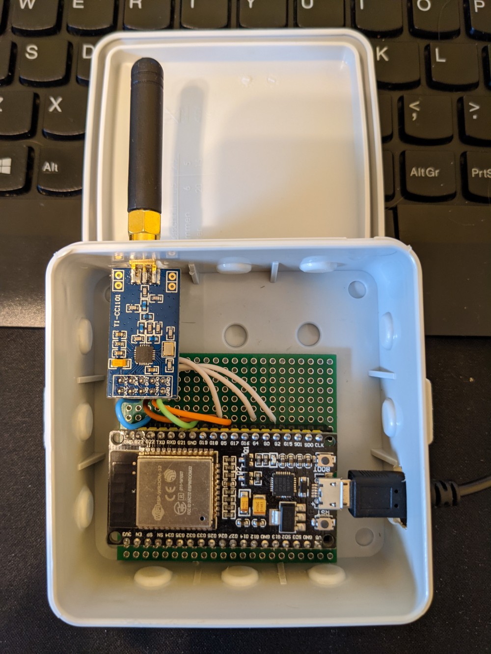
I figured that there was a fun capstone to be done here - the blind reverse engineering and implementation of the protocol my cheep Amazon power switch uses to turn on and off my Christmas Tree. All the work described in this post was done over the course of a few hours thanks to help during the demodulation
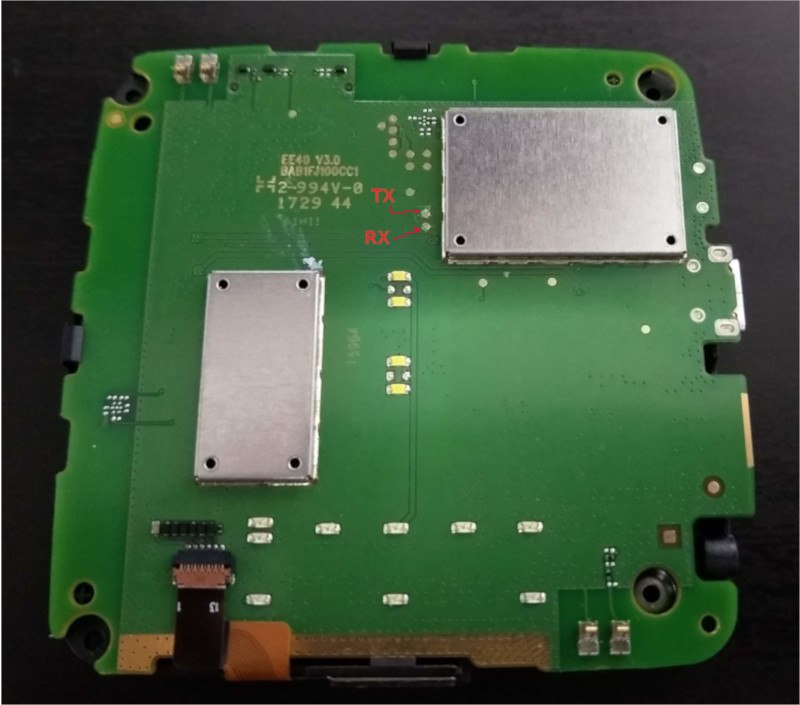
 from Tom Bereknyei and hlieberman.

Going in blind When I first got my switch, I checked it for any FCC markings in order to look up the FCC filings to determine the operational frequency of the device, and maybe some other information such as declared modulation or maybe even part numbers and/or diagrams. However, beyond a few regulatory stickers, there were no FCC ids or other distinguishing IDs on the device. Worse yet, it appeared to be a whitelabeled version of another product, so searching Google for the product name was very unhelpful. Since operation of this device is unlicensed, I figured I d start looking in the ISM band. The most common band used that I ve seen is the band starting at 433.05MHz up to 434.79MHz. I fired up my trusty waterfall tuned to a center frequency of 433.92MHz (since it s right in the middle of the band, and it let me see far enough up and down the band to spot the remote) and pressed a few buttons. Imagine my surprise when I realize the operational frequency of this device is 433.920MHz, exactly dead center. Weird, but lucky! After taking a capture, I started to look at understanding what the modulation type of the signal was, and how I may go about demodulating it.
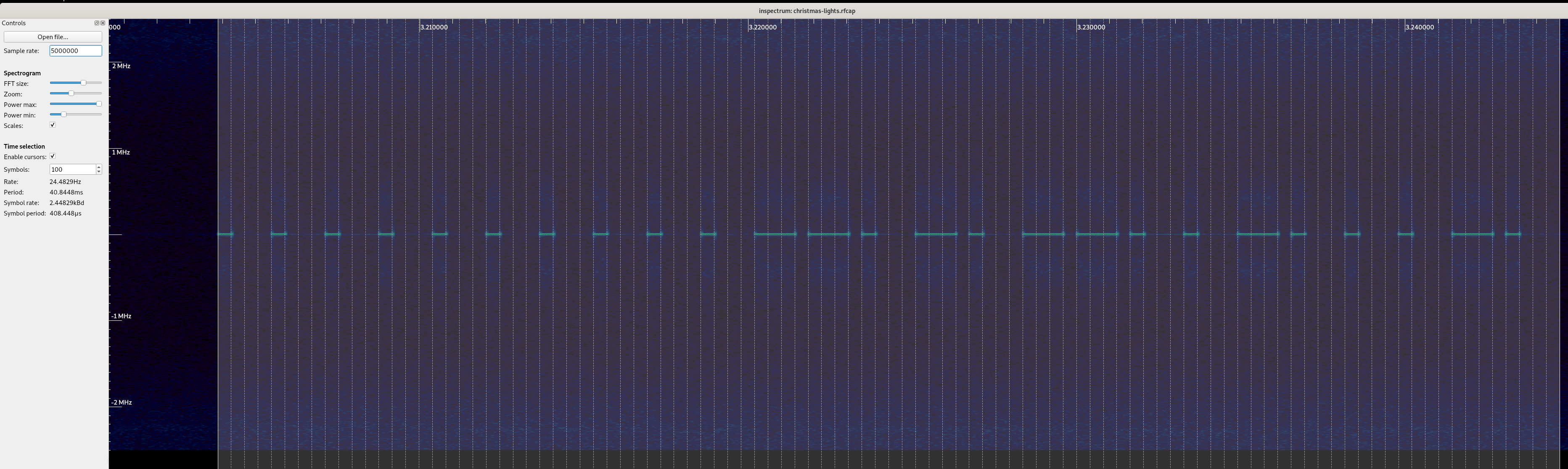
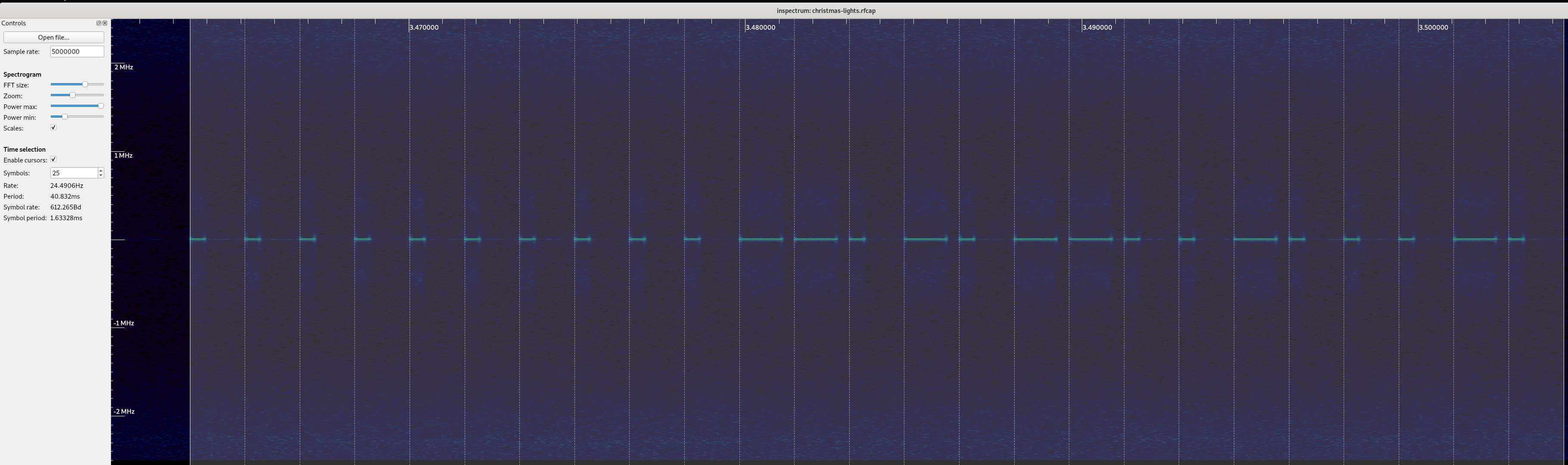
 Using inspectrum, I was able to clearly see the signal in the capture, and it immediately stuck out to my eye to be encoded using OOK / ASK. Next, I started to measure the smallest pulse, and see if I could infer the symbols per second, and try to decode it by hand. These types of signals are generally pretty easy to decode by eye. This wound up giving me symbol rate of 2.2 Ksym/s, which is a lot faster than I expected. While I was working by hand, Tom demodulated a few messages in Python, and noticed that if you grouped the bits into groups of 4, you either had a 1000 or a 1110 which caused me to realize this was encoded using something I saw documented elsewhere, where the 0 is a short pulse, and a 1 is a long pulse, not unlike morse code, but where each symbol takes up a fixed length of time (monospace morse code?). Working on that assumption, I changed my inspectrum symbol width, and demodulated a few more by hand. This wound up demodulating nicely (and the preamble / clock sync could be represented as repeating 0s, which is handy!) and gave us a symbol rate of 612(ish) symbols per second a lot closer to what I was expecting. If we take the code for on in the inspectrum capture above and demodulate it by hand, we get 0000000000110101100100010 (treat a short pulse as a 0, and a long pulse as a 1). If you re interested in following along at home, click on the inspectrum image, and write down the bits you see, and compare it to what I have! Right, so it looks like from what we can tell so far that the packet looks something like this:
preamble / sync
stuff
Next, I took a capture of all the button presses and demodulated them by hand, and put them into a table to try and understand the format of the messages:
Button Demod'd Bits
On 0000000000110101100100010
Off 00000000001101011001010000
Dim Up 0000000000110101100110100
Dim Down 0000000000110101100100100
Timer 1h 0000000000110101100110010
Timer 2h 0000000000110101100100110
Timer 4h 0000000000110101100100000
Dim 100% 0000000000110101000101010
Dim 75% 00000000001101010001001100
Dim 50% 00000000001101010001001000
Dim 25% 0000000000110101000100000
Great! So, this is enough to attempt to control the tree with, I think so I wrote a simple modulator. My approach was to use the fact that I can break down a single symbol into 4 sub-symbol components which is to say, go back to representing a 1 as 1110, and a 0 as 1000. This let me allocate IQ space for the symbol, break the bit into 4 symbols, and if that symbol is 1, write out values from a carrier wave (cos in the real values, and sin in the imaginary values) to the buffer. Now that I can go from bits to IQ data, I can transmit that IQ data using my PlutoSDR or HackRF and try and control my tree. I gave it a try, and the tree blinked off! Success! But wait that s not enough for me I know I can t just demodulate bits and try and replay the bits forever there s stuff like addresses and keys and stuff, and I want to get a second one of these working. Let s take a look at the bits to see if we spot anything fun & interesting. At first glance, a few things jumped out at me as being weird? First is that the preamble is 10 bits long (fine, let s move along - maybe it just needs 8 in a row and there s two to ensure clocks sync?). Next is that the messages are not all the same length. I double (and triple!) checked the messages, and it s true, the messages are not all the same length. Adding an extra bit at the end didn t break anything, but I wonder if that s just due to the implementation rather than the protocol. But, good news, it looks like we have a stable prefix to the messages from the remote must be my device s address! The stable 6 bits that jump out right away are 110101. Something seems weird, though, 6 bits is a bit awkward, even for a bit limited embedded device. Why 6? But hey, wait, we had 10 bits in the preamble, what if we have an 8 bit address meaning my device is 00110101, and the preamble is 8 0 symbols! Those are numbers that someone working on an 8 bit aligned platform would pick! To test this, I added a 0 to the preamble to see if the message starts at the first 1, or if it requires all the bits to be fully decoded, and lo and behold, the tree did not turn on or off. This would seem to me to confirm that the 0s are part of the address, and I can assume we have two 8 bit aligned bytes in the prefix of the message.
preamble / sync
address
stuff
Now, when we go through the 9-10 bits of stuff , we see all sorts of weird bits floating all over the place. The first 4 bits look like it s either 1001 or 0001, but other than that, there s a lot of chaos. This is where things get really squishy. I needed more information to try and figure this out, but no matter how many times I sent a command it was always the same bits (so, no counters), and things feel very opaque still. The only way I was going to make any progress is to get another switch and see how the messages from the remote change. Off to Amazon I went, and ordered another switch from the same page, and eagerly waited its arrival.

Switch #2 The second switch showed up, and I hurriedly unboxed the kit, put batteries into the remote, and fired up my SDR to take a capture. After I captured the first button ( Off ), my heart sunk as I saw my lights connected to Switch #1 flicker off. Apparently the new switch and the old switch have the same exact address. To be sure, I demodulated the messages as before, and came out with the exact same bit pattern. This is a setback and letdown I was hoping to independently control my switches, but it also means I got no additional information about the address or button format. The upside to all of this, though, is that because the switches are controlled by either remote, I only needed one remote, so why not pull it apart and see if I can figure out what components it s using to transmit, and find any datasheets I can. The PCB was super simple, and I wound up finding a WL116SC IC on the PCB. 
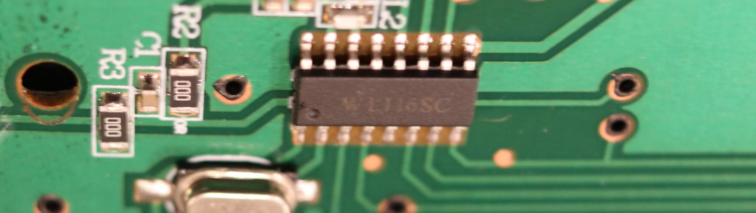
After some googling, I found a single lone datasheet, entirely in Chinese. Thankfully, Google Translate seems to have worked well enough on technical words, and I was able to put together at least a little bit of understanding based on the documentation that was made available. I took a few screenshots below - I put the google translated text above the hanzi. From that sheet, we can see we got the basics of the 1 and 0 symbol encoding right (I was halfway expecting the bits to be flipped), and a huge find by way of a description of the bits in the message! 
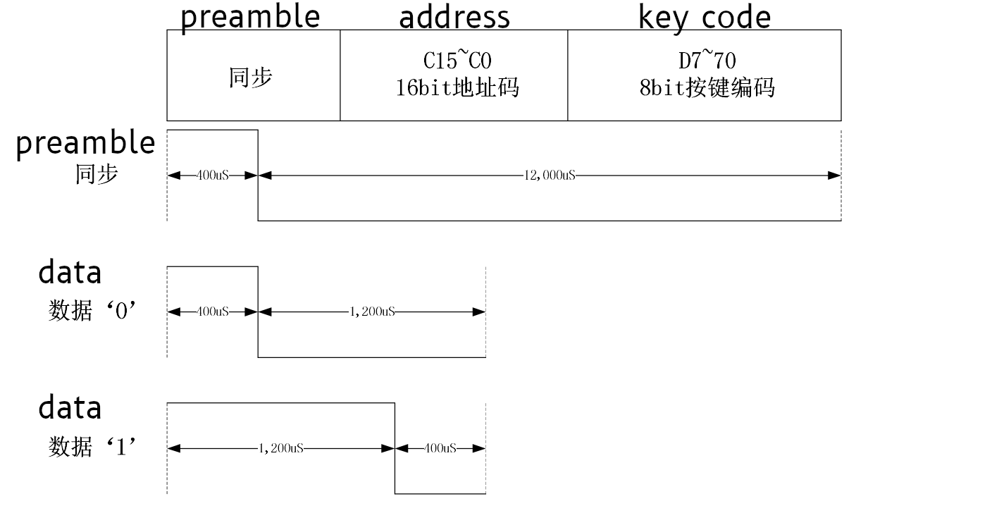
It s a bummer that we missed the clock sync / preamble pulse before the data message, but that s OK somehow. It also turns out that 8 or 10 bit series of of 0"s wasn t clock sync at all - it was part of the address! Since it also turns out that all devices made by this manufacturer have the hardcoded address of []byte 0x00, 0x35 , that means that the vast majority of bits sent are always going to be the same for any button press on any remote made by this vendor. Seems like a waste of bits to me, but hey, what do I know. Additionally, this also tells us the trailing zeros are not part of the data encoding scheme, which is progress!
address
keycode
Now, working on the assumptions validated by the datasheet, here s the updated list of scancodes we ve found:
Button Scancode Bits Integer
On 10010001 145 / 0x91
Off 10010100 148 / 0x94
Dim Up 10011010 154 / 0x9A
Dim Down 10010010 146 / 0x92
Timer 1h 10011001 154 / 0x99
Timer 2h 10010011 147 / 0x93
Timer 4h 10010000 144 / 0x90
Dim 100% 00010101 21 / 0x15
Dim 75% 00010011 19 / 0x13
Dim 50% 00010010 18 / 0x12
Dim 25% 00010000 16 / 0x10
Interestingly, I think the Dim keys may have a confirmation that we have a good demod the codes on the bottom are missing the most significant bit, and when I look back at the scancode table in the datasheet, they make an interesting pattern the bottom two rows, right and left side values match up! If you take a look, Dim 100% is S1 , Dim 75% is S19 , Dim 50% is S8 , and Dim 25% is S20 . Cool! Since none of the other codes line up, I am willing to bet the most significant bit is a Combo indicator, and not part of the button (leaving 7 bits for the keycode). 
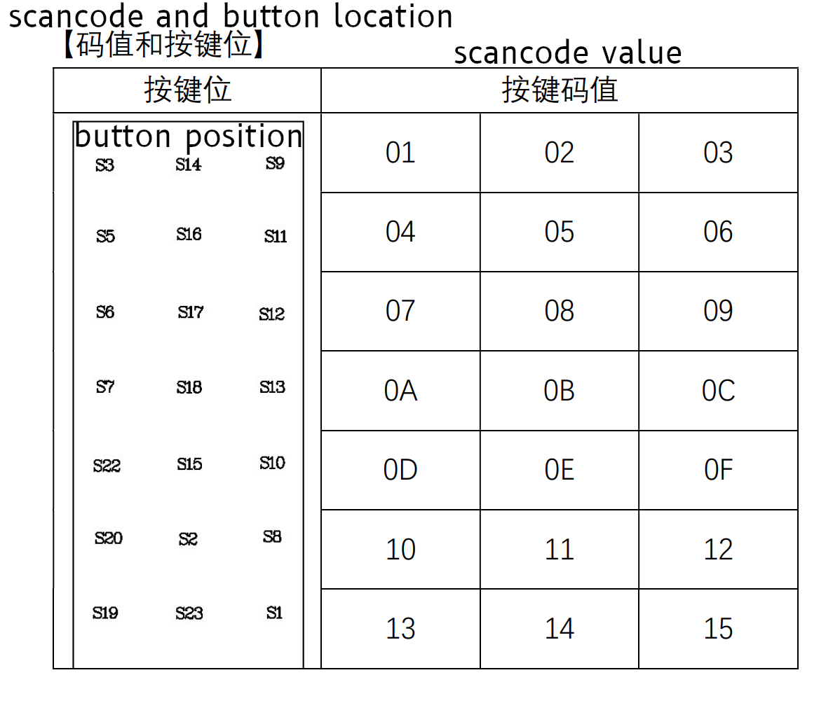
And even more interestingly, one of our scancodes ( Off , which is 0x94) shows up just below this table, in the examples. Over all, I think this tells us we have the right bits to look at for determining the scan code! Great news there!

Back to the modulation! So, armed with this knowledge, I was able to refactor my code to match the timings and understanding outlined by the datasheet and ensure things still work. The switch itself has a high degree of tolerance, so being wildly off frequency or a wildly wrong symbol rate may actually still work. It s hard to know if this is more or less correct, but matching documentation seems like a more stable foundation if nothing else. This code has been really reliable, and tends to work just as well as the remote from what I ve been able to determine. I ve been using incredibly low power to avoid any interference, and it s been very robust - a testament to the engineering that went into the outlet hardware, even though it cost less than of a lot of other switches! I have a lot of respect for the folks who built this device - it s incredibly simple, reliable and my guess is this thing will keep working even in some fairly harsh RF environments. The only downside is the fact the manufacturer used the same address for all their devices, rather than programming a unique address for each outlet and remote when the underlying WL116SC chip supports it. I m sure this was done to avoid complexity in assembly (e.g. pairing the remote and outlet, and having to keep those two items together during assembly), but it s still a bummer. I took apart the switch to see if I could dump an EEPROM and change the address in ROM, but the entire thing was potted in waterproof epoxy, which is a very nice feature if this was ever used outdoors. Not good news for tinkering, though!

Unsolved Mysteries At this point, even though I understand the protocol enough to control the device, it still feels like I hit a dead end in my understanding. I m not able to figure out how exactly the scancodes are implemented, and break them down into more specific parts. They are stable and based on the physical wiring of the remote, so I think I m going to leave it a magic number. I have what I was looking for, and these magic constants appear to be the right one to use, even if I did understand how to create the codes itself. This does leave us with a few bits we never resolved, which I ll memorialize below just to be sure I don t forget about them. Question #1: According to the datasheet there should be a preamble. Why do I not see one leading the first message? My hunch is that the trailing 0 at the end of the payload is actually just the preamble for the next message (always rendering the first message invalid?). This would let us claim there s an engineering reason why we are ignoring the weird bit, and also explain away something from the documentation. It s just weird that it wouldn t be present on the first message. This theory is mostly confirmed by measuring the timing and comparing it to the datasheet, but it s not exactly in line with the datasheet timings either (specifically, it s off by 200 s, which is kinda a lot for a system using 400 s timings). I think I could go either way on the last 0 being the preamble for the next message. It could be that the first message is technically invalid, or it could also be that this was not implemented or actively disabled by the vendor for this specific application / device. It s really hard to know without getting the source code for the WL116SC chip in this specific remote or the source in the outlet itself. Question #2: Why are some keycodes 8 bits and others 9 bits? I still have no idea why there sometimes 8 bits (for instance, On ) and other times there are 9 bits (for instance, Off ) in the 8 bit keycode field. I spent some time playing with the trailing zeros, when I try and send an Off with the most significant 8 bits (without the least significant / last 9th bit, which is a 0 ), it does not turn the tree off. If I send an On with 9 bits (an additional 0 after the least significant bit), it does work, but both On and Off work when I send 10, 11 or 12 bits padded with trailing zeros. I suspect my outlet will ignore data after the switch is done reading bits regardless of trailing zeros. The docs tell me there should only be 8 bits, but it won t work unless I send 9 bits for some commands. There s something fishy going on here, and the datasheet isn t exactly right either way. Question #3: How in the heck do those scancodes work? This one drove me nuts. I ve spent countless hours on trying to figure this out, including emailing the company that makes the WL116SC (they re really nice!), and even though they were super kind and generous with documentation and example source, I m still having a hard time lining up their documentation and examples with what I see from my remote. I think the manufacturer of my remote and switch has modified the protocol enough to where there s actually something different going on here. Bummer. I wound up in my place of last resort asking friends over Signal to try and see if they could find a pattern, as well as making multiple pleas to the twittersphere, to no avail (but thank you to Ben Hilburn, devnulling, Andreas Bombe and Larme for your repiles, help and advice!) I still don t understand how they assemble the scan code for instance, if you merely add, you won t know if a key press of 0x05 is 0x03 + 0x02 or if it s 0x01 + 0x04. On the other hand, treating it as two 4-bit integers won t work for 0x10 to 0x15 (since they need 5 bits to represent). It s also likely the most significant bit is a combo indicator, which only leaves 7 bits for the actual keypress data. Stuffing 10 bits of data into 7 bits is likely resulting in some really intricate bit work. On a last ditch whim, I tried to XOR the math into working, but some initial brute forcing to make the math work given the provided examples did not result in anything. It could be a bitpacked field that I don t understand, but I don t think I can make progress on that without inside knowledge and much more work. Here s the table containing the numbers I was working off of:
Keys Key Codes Scancode
S3 + S9 0x01 + 0x03 0x96
S6 + S12 0x07 + 0x09 0x94
S22 + S10 0x0D + 0x0F 0x3F
If anyone has thoughts on how these codes work, I d love to hear about it! Send me an email or a tweet or something - I m a bit stumped. There s some trick here that is being used to encode the combo key in a way that is decodeable. If it s actually not decodeable (which is a real possibility!), this may act as a unique button combo hash which allows the receiver to not actually determine which keys are pressed, but have a unique button that gets sent when a combo is used. I m not sure I know enough to have a theory as to which it may be.

23 December 2020

Jonathan McDowell: Rooting the Tesco Hudl

Tesco Hudl I have an original Tesco Hudl - a Rockchip RK3188 based Android tablet. It s somewhat long in the tooth and mine is running Android 4.2.2 (Jelly Bean). As a first step in trying to get it updated a bit I decided to root it and have a poke about. There are plenty of guides for this, but they mostly involve downloading Android apps that look dodgy or don t exist any more. Thankfully the bootloader is unlocked, so I did it the hard (manual) way from a Debian 10 (Buster) box. I doubt this is useful to many folk, but I thought I d write it up. As you d expect follow this at your own risk; there is the potential to brick the Hudl. First, enable developer mode on the Hudl (so we can adb in). Open the Settings app, scroll down to the bottom and click About Tablet , scroll down to the bottom and tap Build number 7 times, at which point it will tell you You are now a developer! . Go back to the main settings menu and just above About Tablet there will now be a Developer options entry. Click it, then make sure the box beside USB debugging is ticked. Now you need to install the appropriate tools on your Debian box. That should be:
$ sudo apt install adb rkflashtool
We also need to download a suitable su tool. I lazily went for the prebuilt SuperSU Root:
$ mkdir hudl-root
$ cd hudl-root
$ wget https://supersuroot.org/downloads/SuperSU-v2.79-201612051815.zip
$ unzip SuperSU-v2.79-201612051815.zip
2.82 is the latest version but has problems on Jelly Bean; the device will end up not properly booting. Hook the Hudl up to your machine with a suitable USB cable and you ll now be able to get a shell on it:
$ adb shell
* daemon not running; starting now at tcp:5037
* daemon started successfully
shell@android:/ $
Ctrl-D will quit the shell and return you back to the local prompt. Next step is to reboot into the Rockchip bootloader, and use that to download the system partition (just over 1G in size)
$ adb reboot bootloader
$ sudo rkflashtool r system > system.img
rkflashtool: info: rkflashtool v5.2
rkflashtool: info: Detected RK3188...
rkflashtool: info: interface claimed
rkflashtool: info: working with partition: system
rkflashtool: info: found offset: 0x00142000
rkflashtool: info: found size: 0x00200000
rkflashtool: info: reading flash memory at offset 0x00341fe0... Done!
We now have a system.img file which represents the system partition of the device. We can mount that and copy over the su binary and SuperSU apk.
$ sudo mount -o loop system.img /mnt
$ sudo cp common/Superuser.apk /mnt/app/
$ sudo cp armv7/su /mnt/xbin/
$ sudo chmod +sx /mnt/xbin/su
$ sudo umount /mnt
Finally we can write this image back to the device, reboot and once the reboot has completed use adb to connect and su to root. SuperSU might pop up a dialog on the tablet asking you to ok the action (and possibly indicate it needs to do a fixup of the installation):
$ sudo rkflashtool w system < system.img
$ sudo rkflashtool b
$ adb shell
shell@android:/ $ su -
root@android:/ #

2 November 2020

Vincent Bernat: My collection of vintage PC cards

Recently, I have been gathering some old hardware at my parents house, notably PC extension cards, as they don t take much room and can be converted to a nice display item. Unfortunately, I was not very concerned about keeping stuff around. Compared to all the hardware I have acquired over the years, only a few pieces remain.

Tseng Labs ET4000AX (1989) This SVGA graphics card was installed into a PC powered by a 386SX CPU running at 16 MHz. This was a good card at the time as it was pretty fast. It didn t feature 2D acceleration, unlike the later ET4000/W32. This version only features 512 KB of RAM. It can display 1024 768 images with 16 colors or 800 600 with 256 colors. It was also compatible with CGA, EGA, VGA, MDA, and Hercules modes. No contemporary games were using the SVGA modes but the higher resolutions were useful with Windows 3. This card was manufactured directly by Tseng Labs.
Carte Tseng Labs ET4000AX ISA au-dessus de la bo te "Plan te Aventure"
Tseng Labs ET4000 AX ISA card

AdLib clone (1992) My first sound card was an AdLib. My parents bought it in Canada during the summer holidays in 1992. It uses a Yamaha OPL2 chip to produce sound via FM synthesis. The first game I have tried is Indiana Jones and the Last Crusade. I think I gave this AdLib to a friend once I upgraded my PC with a Sound Blaster Pro 2. Recently, I needed one for a side project, but they are rare and expensive on eBay. Someone mentioned a cheap clone on Vogons, so I bought it. It was sold by Sun Moon Star in 1992 and shipped with a CD-ROM of Doom shareware.
AdLib clone on top of "Alone in the Dark" box
AdLib clone ISA card by Sun Moon Star
On this topic, take a look at OPL2LPT: an AdLib sound card for the parallel port and OPL2 Audio Board: an AdLib sound card for Arduino .

Sound Blaster Pro 2 (1992) Later, I switched the AdLib sound card with a Sound Blaster Pro 2. It features an OPL3 chip and was also able to output digital samples. At the time, this was a welcome addition, but not as important as the FM synthesis introduced earlier by the AdLib.
Sound Blaster Pro 2 on top of "Day of the Tentacle" box
Sound Blaster Pro 2 ISA card

Promise EIDE 2300 Plus (1995) I bought this card mostly for the serial port. I was using a 486DX2 running at 66 MHz with a Creatix LC 288 FC external modem. The serial port was driven by an 8250 UART with no buffer. Thanks to Terminate, I was able to connect to BBSes with DOS, but this was not possible with Windows 3 or OS/2. I needed one of these fancy new cards with a 16550 UART, featuring a 16-byte buffer. At the time, this was quite difficult to find in France. During a holiday trip, I convinced my parent to make a short detour from Los Angeles to San Diego to buy this Promise EIDE 2300 Plus controller card at a shop I located through an advertisement in a local magazine! The card also features an EIDE controller with multi-word DMA mode 2 support. In contrast with the older PIO modes, the CPU didn t have to copy data from disk to memory.
Promise EIDE 2300 Plus next to an OS/2 Warp CD
Promise EIDE 2300 Plus VLB card

3dfx Voodoo2 Magic 3D II (1998) The 3dfx Voodoo2 was one of the first add-in graphics cards implementing hardware acceleration of 3D graphics. I bought it from a friend along with his Pentium II box in 1999. It was a big evolutionary step in PC gaming, as games became more beautiful and fluid. A traditional video controller was still required for 2D. A pass-through VGA cable daisy-chained the video controller to the Voodoo, which was itself connected to the monitor.
3dfx Voodoo 2 Magic 3D II on top of "Jedi Knight: Dark Forces II" box
3dfx Voodoo2 Magic 3D II PCI card

3Com 3C905C-TX-M Tornado (1999) In the early 2000s, in college, the Internet connection on the campus was provided by a student association through a 100 Mbps Ethernet cable. If you wanted to reach the maximum speed, the 3Com 3C905C-TX-M PCI network adapter, nicknamed Tornado , was the card you needed. We would buy it second-hand by the dozen and sell them to other students for around 30 .
3COM 3C905C-TX-M on top of "Red Alert" box
3Com 3C905C-TX-M PCI card

19 October 2020

Louis-Philippe V ronneau: Musings on long-term software support and economic incentives

Although I still read a lot, during my college sophomore years my reading habits shifted from novels to more academic works. Indeed, reading dry textbooks and economic papers for classes often kept me from reading anything else substantial. Nowadays, I tend to binge read novels: I won't touch a book for months on end, and suddenly, I'll read 10 novels back to back1. At the start of a novel binge, I always follow the same ritual: I take out my e-reader from its storage box, marvel at the fact the battery is still pretty full, turn on the WiFi and check if there are OS updates. And I have to admit, Kobo Inc. (now Rakuten Kobo) has done a stellar job of keeping my e-reader up to date. I've owned this model (a Kobo Aura 1st generation) for 7 years now and I'm still running the latest version of Kobo's Linux-based OS. Having recently had trouble updating my Nexus 5 (also manufactured 7 years ago) to Android 102, I asked myself:
Why is my e-reader still getting regular OS updates, while Google stopped issuing security patches for my smartphone four years ago?
To try to answer this, let us turn to economic incentives theory. Although not the be-all and end-all some think it is3, incentives theory is not a bad tool to analyse this particular problem. Executives at Google most likely followed a very business-centric logic when they decided to drop support for the Nexus 5. Likewise, Rakuten Kobo's decision to continue updating older devices certainly had very little to do with ethics or loyalty to their user base. So, what are the incentives that keep Kobo updating devices and why are they different than smartphone manufacturers'? A portrait of the current long-term software support offerings for smartphones and e-readers Before delving deeper in economic theory, let's talk data. I'll be focusing on 2 brands of e-readers, Amazon's Kindle and Rakuten's Kobo. Although the e-reader market is highly segmented and differs a lot based on geography, Amazon was in 2015 the clear worldwide leader with 53% of the worldwide e-reader sales, followed by Rakuten Kobo at 13%4. On the smartphone side, I'll be differentiating between Apple's iPhones and Android devices, taking Google as the barometer for that ecosystem. As mentioned below, Google is sadly the leader in long-term Android software support. Rakuten Kobo According to their website and to this Wikipedia table, the only e-readers Kobo has deprecated are the original Kobo eReader and the Kobo WiFi N289, both released in 2010. This makes their oldest still supported device the Kobo Touch, released in 2011. In my book, that's a pretty good track record. Long-term software support does not seem to be advertised or to be a clear selling point in their marketing. Amazon According to their website, Amazon has dropped support for all 8 devices produced before the Kindle Paperwhite 2nd generation, first sold in 2013. To put things in perspective, the first Kindle came out in 2007, 3 years before Kobo started selling devices. Like Rakuten Kobo, Amazon does not make promises of long-term software support as part of their marketing. Apple Apple has a very clear software support policy for all their devices:
Owners of iPhone, iPad, iPod or Mac products may obtain a service and parts from Apple or Apple service providers for five years after the product is no longer sold or longer, where required by law.
This means in the worst-case scenario of buying an iPhone model just as it is discontinued, one would get a minimum of 5 years of software support. Android Google's policy for their Android devices is to provide software support for 3 years after the launch date. If you buy a Pixel device just before the new one launches, you could theoretically only get 2 years of support. In 2018, Google decided OEMs would have to provide security updates for at least 2 years after launch, threatening not to license Google Apps and the Play Store if they didn't comply. A question of cost structure From the previous section, we can conclude that in general, e-readers seem to be supported longer than smartphones, and that Apple does a better job than Android OEMs, providing support for about twice as long. Even Fairphone, who's entire business is to build phones designed to last and to be repaired was not able to keep the Fairphone 1 (2013) updated for more than a couple years and seems to be struggling to keep the Fairphone 2 (2015) running an up to date version of Android. Anyone who has ever worked in IT will tell you: maintaining software over time is hard work and hard work by specialised workers is expensive. Most commercial electronic devices are sold and developed by for-profit enterprises and software support all comes down to a question of cost structure. If companies like Google or Fairphone are to be expected to provide long-term support for the devices they manufacture, they have to be able to fund their work somehow. In a perfect world, people would be paying for the cost of said long-term support, as it would likely be cheaper then buying new devices every few years and would certainly be better for the planet. Problem is, manufacturers aren't making them pay for it. Economists call this type of problem externalities: things that should be part of the cost of a good, but aren't for one a reason or another. A classic example of an externality is pollution. Clearly pollution is bad and leads to horrendous consequences, like climate change. Sane people agree we should drastically cut our greenhouse gas emissions, and yet, we aren't. Neo-classical economic theory argues the way to fix externalities like pollution is to internalise these costs, in other words, to make people pay for the "real price" of the goods they buy. In the case of climate change and pollution, neo-classical economic theory is plain wrong (spoiler alert: it often is), but this is where band-aids like the carbon tax comes from. Still, coming back to long-term software support, let's see what would happen if we were to try to internalise software maintenance costs. We can do this multiple ways. 1 - Include the price of software maintenance in the cost of the device This is the choice Fairphone makes. This might somewhat work out for them since they are a very small company, but it cannot scale for the following reasons:
  1. This strategy relies on you giving your money to an enterprise now, and trusting them to "Do the right thing" years later. As the years go by, they will eventually look at their books, see how much ongoing maintenance is costing them, drop support for the device, apologise and move on. That is to say, enterprises have a clear economic incentive to promise long-term support and not deliver. One could argue a company's reputation would suffer from this kind of behaviour. Maybe sometime it does, but most often people forget. Political promises are a great example of this.
  2. Enterprises go bankrupt all the time. Even if company X promises 15 years of software support for their devices, if they cease to exist, your device will stop getting updates. The internet is full of stories of IoT devices getting bricked when the parent company goes bankrupt and their servers disappear. This is related to point number 1: to some degree, you have a disincentive to pay for long-term support in advance, as the future is uncertain and there are chances you won't get the support you paid for.
  3. Selling your devices at a higher price to cover maintenance costs does not necessarily mean you will make more money overall raising more money to fund maintenance costs being the goal here. To a certain point, smartphone models are substitute goods and prices higher than market prices will tend to drive consumers to buy cheaper ones. There is thus a disincentive to include the price of software maintenance in the cost of the device.
  4. People tend to be bad at rationalising the total cost of ownership over a long period of time. Economists call this phenomenon hyperbolic discounting. In our case, it means people are far more likely to buy a 500$ phone each 3 years than a 1000$ phone each 10 years. Again, this means OEMs have a clear disincentive to include the price of long-term software maintenance in their devices.
Clearly, life is more complex than how I portrayed it: enterprises are not perfect rational agents, altruism exists, not all enterprises aim solely for profit maximisation, etc. Still, in a capitalist economy, enterprises wanting to charge for software maintenance upfront have to overcome these hurdles one way or another if they want to avoid failing. 2 - The subscription model Another way companies can try to internalise support costs is to rely on a subscription-based revenue model. This has multiple advantages over the previous option, mainly:
  1. It does not affect the initial purchase price of the device, making it easier to sell them at a competitive price.
  2. It provides a stable source of income, something that is very valuable to enterprises, as it reduces overall risks. This in return creates an incentive to continue providing software support as long as people are paying.
If this model is so interesting from an economic incentives point of view, why isn't any smartphone manufacturer offering that kind of program? The answer is, they are, but not explicitly5. Apple and Google can fund part of their smartphone software support via the 30% cut they take out of their respective app stores. A report from Sensor Tower shows that in 2019, Apple made an estimated US$ 16 billion from the App Store, while Google raked in US$ 9 billion from the Google Play Store. Although the Fortune 500 ranking tells us this respectively is "only" 5.6% and 6.5% of their gross annual revenue for 2019, the profit margins in this category are certainly higher than any of their other products. This means Google and Apple have an important incentive to keep your device updated for some time: if your device works well and is updated, you are more likely to keep buying apps from their store. When software support for a device stops, there is a risk paying customers will buy a competitor device and leave their ecosystem. This also explains why OEMs who don't own app stores tend not to provide software support for very long periods of time. Most of them only make money when you buy a new phone. Providing long-term software support thus becomes a disincentive, as it directly reduces their sale revenues. Same goes for Kindles and Kobos: the longer your device works, the more money they make with their electronic book stores. In my opinion, it's likely Amazon and Rakuten Kobo produce quarterly cost-benefit reports to decide when to drop support for older devices, based on ongoing support costs and the recurring revenues these devices bring in. Rakuten Kobo is also in a more precarious situation than Amazon is: considering Amazon's very important market share, if your device stops getting new updates, there is a greater chance people will replace their old Kobo with a Kindle. Again, they have an important economic incentive to keep devices running as long as they are profitable. Can Free Software fix this? Yes and no. Free Software certainly isn't a magic wand one can wave to make everything better, but does provide major advantages in terms of security, user freedom and sometimes costs. The last piece of the puzzle explaining why Rakuten Kobo's software support is better than Google's is technological choices. Smartphones are incredibly complex devices and have become the main computing platform of many. Similar to the web, there is a race for features and complexity that tends to create bloat and make older devices slow and painful to use. On the other hand, e-readers are simpler devices built for a single task: display electronic books. Control over the platform is also a key aspect of the cost structure of providing software updates. Whereas Apple controls both the software and hardware side of iPhones, Android is a sad mess of drivers and SoCs, all providing different levels of support over time6. If you take a look at the platforms the Kindle and Kobo are built on, you'll quickly see they both use Freescale I.MX SoCs. These processors are well known for their excellent upstream support in the Linux kernel and their relative longevity, chips being produced for either 10 or 15 years. This in turn makes updates much easier and less expensive to provide. So clearly, open architectures, free drivers and open hardware helps tremendously, but aren't enough on their own. One of the lessons we must learn from the (amazing) LineageOS project is how lack of funding hurts everyone. If there is no one to do the volunteer work required to maintain a version of LOS for your device, it won't be supported. Worse, when purchasing a new device, users cannot know in advance how many years of LOS support they will get. This makes buying new devices a frustrating hit-and-miss experience. If you are lucky, you will get many years of support. Otherwise, you risk your device becoming an expensive insecure paperweight. So how do we fix this? Anyone with a brain understands throwing away perfectly good devices each 2 years is not sustainable. Government regulations enforcing a minimum support life would be a step in the right direction, but at the end of the day, Capitalism is to blame. Like the aforementioned carbon tax, band-aid solutions can make things somewhat better, but won't fix our current economic system's underlying problems. For now though, I'll leave fixing the problem of Capitalism to someone else.

  1. My most recent novel binge has been focused on re-reading the Dune franchise. I first read the 6 novels written by Frank Herbert when I was 13 years old and only had vague and pleasant memories of his work. Great stuff.
  2. I'm back on LineageOS! Nice folks released an unofficial LOS 17.1 port for the Nexus 5 last January and have kept it updated since then. If you are to use it, I would also recommend updating TWRP to this version specifically patched for the Nexus 5.
  3. Very few serious economists actually believe neo-classical rational agent theory is a satisfactory explanation of human behavior. In my opinion, it's merely a (mostly flawed) lens to try to interpret certain behaviors, a tool amongst others that needs to be used carefully, preferably as part of a pluralism of approaches.
  4. Good data on the e-reader market is hard to come by and is mainly produced by specialised market research companies selling their findings at very high prices. Those particular statistics come from a MarketWatch analysis.
  5. If they were to tell people: You need to pay us 5$/month if you want to receive software updates, I'm sure most people would not pay. Would you?
  6. Coming back to Fairphones, if they had so much problems providing an Android 9 build for the Fairphone 2, it's because Qualcomm never provided Android 7+ support for the Snapdragon 801 SoC it uses.

Next.

Previous.